The utilization factor is fundamental in lighting, defining efficiency of luminaires across architectural and industrial applications. Accurate calculation ensures compliance with CIE, EN, and IES standards while maximizing modern LED lighting efficiency.
Utilization Factor (UF) Calculator — Luminaires
Quickly compute the Utilization Factor (UF), convert emitted lumens to delivered flux, or find the UF required to meet a target illuminance. Designed for lighting designers and electrical engineers.
| Scenario | Value |
|---|
Delivered flux: Φdelivered = Φemitted × UF.
From illuminance: UF = (E × A) / (N × Φ × MF) — where MF is the maintenance factor.
What is Utilization Factor (UF)?
Which MF should I use?
Why does UF vary with room geometry?
What Is the Utilization Factor?
The utilization factor (UF) is defined as the ratio between the luminous flux reaching the working plane (Φ_wp) and the total luminous flux emitted by the lamps or LED modules of the luminaire (Φ_total):
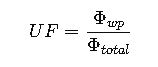
- Φ_wp = luminous flux reaching the working plane (lm)
- Φ_total = total luminous flux emitted by the lamps or LED source (lm)
In practice, UF values typically range between 0.3 and 0.8 depending on luminaire type, optics, mounting height, reflectance, and room index.
Detailed Formula Set for Utilization Factor Calculations
Lighting engineers rarely use only the base formula. A set of interdependent equations is needed to compute UF accurately within the context of lighting design. Below are the key formulas:
1. Room Index (K)
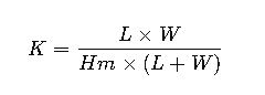
Where:
- L = room length (m)
- W = room width (m)
- Hm = mounting height = luminaire height above working plane (m)
Typical values of K range between 0.6 (long narrow rooms) and 5.0 (square compact rooms).
2. Utilization Factor Dependency
The UF is tabulated in manufacturer photometric data as a function of:
- Room Index (K)
- Reflectance of ceiling (ρc)
- Reflectance of walls (ρw)
- Reflectance of floor/working plane (ρf)
Thus, UF is not a constant; it is interpolated from manufacturer tables or computed through lighting software (Dialux, Relux, AGi32).
3. Average Illuminance (E)
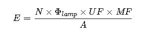
Where:
- E = average illuminance on the working plane (lux)
- N = number of luminaires
- Φ_lamp = luminous flux per luminaire (lm)
- UF = utilization factor (dimensionless)
- MF = maintenance factor (0.6 – 0.9 typical range)
- A = area of the working plane (m²)
This links UF directly with real design outcomes.
Typical Values of Reflectance and UF
Below is a comprehensive table compiling common values used in practice. These are approximations drawn from CIE technical reports and IESNA Lighting Handbook.
Table 1 – Typical Surface Reflectance Values
| Surface | Common Material/Finish | Reflectance (ρ) |
|---|---|---|
| Ceiling (white paint) | Matte white emulsion | 0.7 – 0.85 |
| Ceiling (medium) | Off-white, acoustic tiles | 0.6 – 0.7 |
| Ceiling (dark) | Wood, exposed concrete | 0.3 – 0.5 |
| Walls (light) | White paint, plaster | 0.5 – 0.7 |
| Walls (medium) | Beige, pastel tones | 0.3 – 0.5 |
| Walls (dark) | Brick, wood panel | 0.1 – 0.3 |
| Floor (light) | Light vinyl, polished tiles | 0.3 – 0.4 |
| Floor (medium) | Gray concrete, medium wood | 0.2 – 0.3 |
| Floor (dark) | Asphalt, dark carpet | 0.1 – 0.2 |
Table 2 – Example Utilization Factor Values for a Typical Recessed LED Luminaire
Assumptions:
- Symmetric wide-beam distribution
- Ceiling reflectance ρc = 0.7
- Wall reflectance ρw = 0.5
- Floor reflectance ρf = 0.2
| Room Index (K) | UF Value |
|---|---|
| 0.75 | 0.46 |
| 1.0 | 0.52 |
| 1.25 | 0.57 |
| 1.5 | 0.61 |
| 2.0 | 0.66 |
| 2.5 | 0.69 |
| 3.0 | 0.71 |
| 4.0 | 0.74 |
| 5.0 | 0.76 |
Table 3 – Comparison of UF Values for Different Luminaire Types
| Luminaire Type | Distribution Type | Typical UF Range |
|---|---|---|
| Recessed LED Panel | Direct wide-beam | 0.6 – 0.8 |
| Suspended Direct/Indirect | Mixed beam | 0.45 – 0.65 |
| Industrial High-Bay LED | Narrow beam | 0.3 – 0.55 |
| Wall-mounted Batten | Asymmetric | 0.4 – 0.6 |
| Outdoor Floodlight | Narrow/Wide | 0.2 – 0.5 |
Why Utilization Factor Matters in Practice
- Energy optimization: Higher UF reduces the number of luminaires needed.
- Uniformity control: UF tables guide placement for avoiding dark zones.
- Compliance: Regulatory frameworks (e.g., EN 12464-1 for workplaces) require calculated illuminance, which depends on UF.
- Economic design: Overestimating UF leads to under-illumination, while underestimating it increases project cost unnecessarily.
Real-World Application of Utilization Factor in Luminaires
The theoretical framework of UF only becomes meaningful when translated into real-world lighting design scenarios. Engineers and lighting consultants rely on UF tables and manufacturer photometric data to determine the number and type of luminaires required to achieve compliance with workplace standards. Below, we explore two detailed case studies that show how UF affects project outcomes in both commercial and industrial environments.
Case Study 1 – Open Plan Office with LED Panel Luminaires
Scenario
- Space dimensions: 18 m (length) × 12 m (width)
- Ceiling height: 3.2 m
- Working plane height: 0.8 m (desk level)
- Ceiling reflectance: 0.7 (white acoustic tiles)
- Wall reflectance: 0.5 (light paint)
- Floor reflectance: 0.2 (gray carpet)
- Task requirement: 500 lux average illuminance (as per EN 12464-1 Office Lighting Standard)
Design Considerations
- Selected luminaire: Recessed LED panel, 600 × 600 mm, luminous flux ≈ 4000 lm each.
- Mounting: Direct installation into modular ceiling.
- Utilization factor (from manufacturer table): ≈ 0.65 for room index near 1.5 with given reflectances.
Implementation Strategy
- Designers calculate the number of luminaires required, taking into account UF and maintenance factors.
- UF ensures that light losses due to room geometry and reflectance are compensated.
- With a UF close to 0.65, this luminaire is highly efficient in translating lamp lumens into usable workplace illumination.
Outcome
- The office achieves excellent visual comfort, uniform illumination, and compliance with regulatory lux levels.
- By choosing a luminaire with a higher UF, the total number of fittings required was reduced, leading to lower installation and operational costs.
Key Insight
UF plays a decisive role in making design energy-efficient and cost-optimized. If a luminaire with a UF of 0.45 had been selected, approximately 30% more luminaires would have been needed to meet the same lux target.
Case Study 2 – Industrial High-Bay Warehouse
Scenario
- Space dimensions: 40 m (length) × 30 m (width)
- Mounting height: 12 m (high-bay ceiling)
- Working plane: 1 m above floor (loading/unloading operations)
- Ceiling reflectance: 0.5 (painted steel)
- Wall reflectance: 0.3 (exposed concrete)
- Floor reflectance: 0.2 (epoxy-coated slab)
- Task requirement: 300 lux (according to IES and EN guidelines for warehouses with medium visual tasks)
Design Considerations
- Selected luminaire: High-bay LED fixture, narrow-beam optic, luminous flux ≈ 20,000 lm.
- Utilization factor (manufacturer data): ≈ 0.40 at this room index due to high mounting height and lower wall reflectance.
Implementation Strategy
- Because UF is considerably lower than in office applications, more powerful luminaires or higher quantities are required.
- Beam distribution is carefully chosen to minimize spill light and ensure light reaches the working plane effectively.
Outcome
- Achieved target illuminance of 300 lux with uniformity suitable for industrial tasks.
- Although the UF is modest (0.40), careful luminaire selection and spacing maintained compliance while avoiding unnecessary over-lighting.
Key Insight
Industrial projects highlight the limitations of UF in large volumes. High ceilings, low reflectances, and narrow beams reduce UF significantly, demanding precise design to balance performance and cost.
Extended Factors Influencing Utilization Factor
While surface reflectance, room index, and luminaire type are the most cited parameters, professional lighting design recognizes additional influences on UF:
- Mounting position: Suspended versus recessed installation can alter the interaction of light with surfaces.
- Luminaire shielding angle: Deeper recess or shielding can reduce direct luminous flux reaching the working plane.
- Optical efficiency: Advanced LED optics improve UF compared to legacy fluorescent fittings.
- Color of finishes over time: Dust accumulation or repainting of surfaces changes reflectance, indirectly affecting UF.
- Maintenance practices: Clean luminaires and surfaces preserve higher effective UF across the project lifetime.
Comparison of Utilization Factor Across Applications
To appreciate the variability of UF in practice, the following table summarizes application-based UF ranges commonly observed in design software simulations and manufacturer datasheets:
Table 4 – Typical UF Ranges by Application
| Application | Typical UF Range | Notes |
|---|---|---|
| Open-plan office | 0.60 – 0.75 | High ceiling reflectance, wide-beam luminaires. |
| Classrooms | 0.55 – 0.70 | Moderate reflectance, ceiling-mounted luminaires. |
| Hospitals and clinics | 0.50 – 0.70 | Neutral finishes, need uniformity for hygiene tasks. |
| Retail environments | 0.45 – 0.65 | Accent lighting reduces average UF. |
| Warehouses (high-bay) | 0.30 – 0.50 | High mounting height lowers UF. |
| Parking garages | 0.35 – 0.55 | Dark surfaces absorb significant light. |
| Outdoor floodlighting | 0.20 – 0.40 | Very low reflectances and open geometry. |
Professional Best Practices for Maximizing UF
- Select appropriate optics: Wide-beam optics maximize UF in low/medium spaces, while narrow-beam optics are suitable for high ceilings.
- Optimize surface reflectances: Use light-colored finishes for ceilings and walls to raise UF significantly.
- Design for maintainability: Regular cleaning schedules prevent UF degradation due to dust or dirt accumulation.
- Leverage software: Tools such as DIALux, Relux, and AGi32 interpolate manufacturer photometry to provide precise UF values.
- Validate with standards: Always cross-check against EN 12464-1, CIE Technical Reports, and IESNA recommendations.