Transformer losses impact energy efficiency, operational costs, and the overall reliability of electrical power systems.
This article examines iron and copper losses with formulas, tables, variable definitions, and practical application examples.
Transformer Losses Calculator
Extensive Tables of Common Transformer Loss Values
Understanding typical values for iron and copper losses across various transformer ratings, voltage levels, and designs is crucial for accurate loss calculations and benchmarking. Below are detailed tables presenting commonly encountered loss values in transformers.
Table 1: Typical Iron Loss Values (Core Losses) in Transformers
| Transformer Rating (kVA) | Voltage Level (kV) | Iron Loss (W) | Core Material Type | Typical Frequency (Hz) | Remarks |
|---|---|---|---|---|---|
| 25 | 0.4 | 40 | CRGO Steel | 50 | Distribution transformer, low-loss |
| 50 | 11 | 80 | CRGO Steel | 50 | Distribution, improved core design |
| 100 | 33 | 120 | Amorphous Steel | 50 | Medium power, advanced core |
| 250 | 33 | 250 | CRGO Steel | 60 | Industrial transformer, 60 Hz |
| 500 | 66 | 450 | Amorphous Steel | 50 | Large distribution transformer |
| 1000 | 132 | 700 | CRGO Steel | 50 | Power transformer, typical losses |
| 2000 | 220 | 1200 | Amorphous Steel | 50 | Utility-scale power transformer |
Notes:
- CRGO = Cold Rolled Grain Oriented Steel, standard core material.
- Amorphous steel is known for significantly reducing core losses.
Table 2: Typical Copper Loss Values (Winding Losses) in Transformers
| Transformer Rating (kVA) | Primary Current (A) | Secondary Current (A) | Copper Loss (W) | Winding Material | Operating Temperature (°C) | Remarks |
|---|---|---|---|---|---|---|
| 25 | 36 | 60 | 120 | Copper | 75 | Small distribution transformer |
| 50 | 72 | 120 | 240 | Copper | 85 | Improved winding design |
| 100 | 144 | 208 | 480 | Copper | 90 | Medium power |
| 250 | 360 | 416 | 1200 | Copper | 95 | Industrial grade |
| 500 | 720 | 832 | 2400 | Copper | 100 | Larger units |
| 1000 | 1440 | 1664 | 4800 | Copper | 105 | Utility-scale power |
Detailed Formulas for Calculation of Transformer Losses (Iron and Copper)
The calculation of transformer losses requires understanding two main types of losses:
- Iron Losses (Core Losses): Caused by hysteresis and eddy currents in the core.
- Copper Losses (Winding Losses): Result from resistance in the transformer windings when carrying load current.
1. Iron Loss Calculation
Iron losses are generally considered constant and independent of the load current, but dependent on voltage and frequency.

Each component can be expressed as:
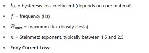
- Hysteresis Loss:
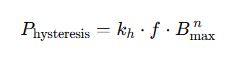
Where:
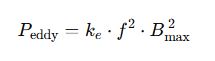
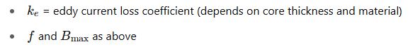
Where:
Total Iron Loss Approximation:
In practical transformer calculations, iron losses are often directly measured or provided, but can be approximated by:

Where kf and x are empirically derived constants based on core material and construction.
2. Copper Loss Calculation
Copper losses are dependent on the load current and winding resistance:
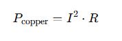
Where:
- I= current through the winding (A)
- R= resistance of the winding (Ω) at operating temperature
Copper loss increases with the square of the load current, making it highly significant at high loads.
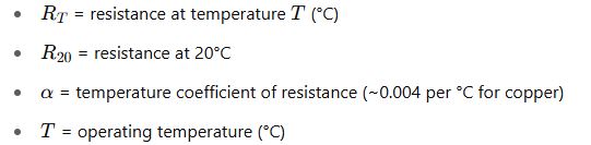
Resistance Temperature Correction:
Transformer winding resistance changes with temperature:
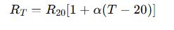
Where:
This formula is critical for accurate copper loss calculations.
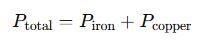
3. Total Transformer Losses
The total losses in a transformer under load are the sum of iron and copper losses:
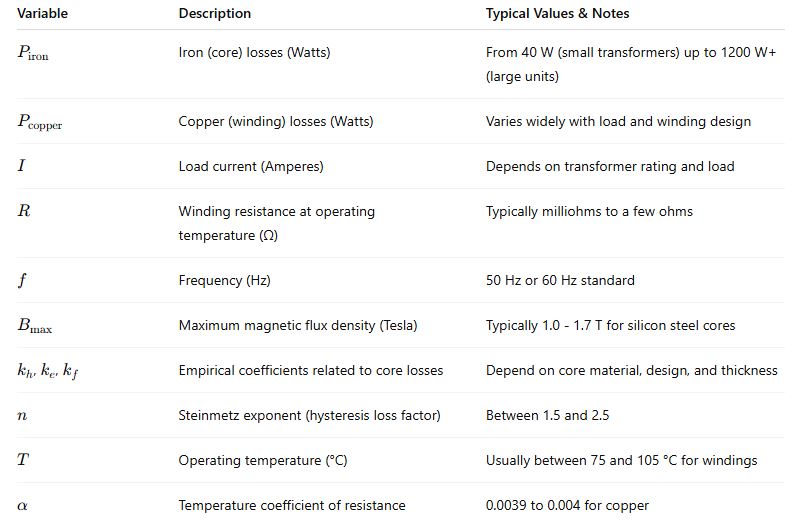
Explanation of Variables and Typical Values
Real-World Application Examples
Example 1: Calculating Losses in a 100 kVA, 11 kV Transformer
Given:
- Transformer rating: 100 kVA
- Primary voltage: 11 kV
- Frequency: 50 Hz
- Core losses (from test): 120 W
- Winding resistance at 20°C: 0.5 Ω
- Operating temperature: 90°C
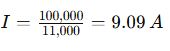
- Load current at rated load:
Calculate:
- Copper losses at rated load
- Total losses
Step 1: Calculate winding resistance at 90°C

Step 2: Copper losses

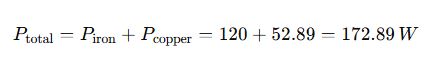
Step 3: Total losses
Example 2: Transformer Loss Estimation for a 500 kVA, 33 kV Distribution Transformer
Given:
- Transformer rating: 500 kVA
- Primary voltage: 33 kV
- Frequency: 50 Hz
- Iron losses: 450 W (from design data)
- Winding resistance at 20°C: 0.12 Ω (primary winding)
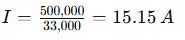
- Load current at rated load:
- Operating temperature: 95°C
Calculate copper loss and total losses.
Step 1: Correct resistance for temperature

Step 2: Copper losses

Step 3: Total losses
Additional Technical Details
Core Loss Reduction Techniques
- Use of amorphous steel cores to reduce eddy current losses.
- Thin laminations to minimize eddy currents.
- Optimized core design to reduce magnetic flux density peaks.
Copper Loss Optimization
- Increasing conductor cross-sectional area reduces resistance.
- Use of high-purity copper or aluminum with suitable skin effect considerations.
- Proper cooling to maintain lower winding temperatures, reducing resistance.
Authoritative External References
- IEEE Standard C57.12.00-2015: “IEEE Standard for General Requirements for Liquid-Immersed Distribution, Power, and Regulating Transformers”
- IEC 60076-1: “Power Transformers – Part 1: General”
- Electrical4U Transformer Losses
- IEEE Xplore Digital Library for latest research on transformer efficiency