Total Harmonic Distortion (THD) affects power quality, equipment performance, and compliance with international harmonic standards.
This guide explains THD principles, formulas, and real-world cases for accurate and standards-compliant electrical system design.
Total Harmonic Distortion (THD) Calculator
Extensive Tables of Common THD Values in Electrical Systems
The following tables list typical THD values for various electrical systems, devices, and voltage levels, categorized by application, source type, and compliance status.
Table 1. Common THD Voltage Levels per IEEE 519 (2022)
| System Voltage (kV) | Point of Common Coupling (PCC) | Max THD Voltage (%) | Max Individual Harmonic (%) |
|---|---|---|---|
| < 1 kV | Low-voltage distribution | 5.0 | 3.0 |
| 1 kV – 69 kV | Medium-voltage distribution | 3.0 | 1.5 |
| 69 kV – 161 kV | Subtransmission | 2.5 | 1.0 |
| > 161 kV | Transmission | 1.5 | 0.5 |
Table 2. Typical THD Current Levels per IEEE 519 (2022)
| I_SC / I_L Ratio | Total Demand Distortion (TDD %) Limit |
|---|---|
| < 20 | 5.0 |
| 20 – 50 | 8.0 |
| 50 – 100 | 12.0 |
| 100 – 1000 | 15.0 |
| > 1000 | 20.0 |
Note:
- I<sub>SC</sub>: Short-circuit current at PCC
- I<sub>L</sub>: Maximum demand load current (fundamental only)
Table 3. THD Ranges by Equipment Type
| Device | Typical THD (Voltage) | Typical THD (Current) |
|---|---|---|
| Linear loads (resistive) | < 1% | < 5% |
| Office equipment (PCs, monitors) | 2% – 5% | 50% – 80% |
| LED lighting systems | 2% – 7% | 30% – 70% |
| Variable Frequency Drives (VFDs) | 1% – 4% | 40% – 100% |
| UPS Systems (Double Conversion) | < 3% | 30% – 60% |
| Photovoltaic Inverters | < 3% | 20% – 40% |
Table 4. Harmonic Orders and Their Effects
| Harmonic Order | Type | Frequency (Hz) | Typical Sources | System Impact |
|---|---|---|---|---|
| 3rd | Triplen | 150 (for 50 Hz) | Fluorescent lighting, PCs | Neutral overload, overheating |
| 5th | Negative seq | 250 (for 50 Hz) | Drives, inverters | Transformer derating, torque ripple |
| 7th | Negative seq | 350 (for 50 Hz) | UPS, VFDs | Voltage distortion |
| 11th, 13th | Higher order | > 500 | Large data centers, arc furnaces | Equipment malfunction, relay misoperation |
Formulas for THD Calculation and Variable Definitions
The calculation of Total Harmonic Distortion requires a solid understanding of harmonic spectra and root-mean-square (RMS) values.
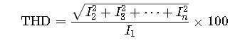
1. Voltage or Current THD Calculation

or for current:
Where:
| Variable | Definition | Typical Range |
|---|---|---|
| V<sub>1</sub> / I<sub>1</sub> | RMS of fundamental frequency component (50 Hz or 60 Hz) | Base reference value |
| V<sub>n</sub>, I<sub>n</sub> | RMS of nth harmonic voltage/current component | 0 – 40% of V₁/I₁ |
| n | Harmonic order (2, 3, 4…) | Up to 50 or 63 harmonics |
2. THD Including the Fundamental (Alternate Definition)
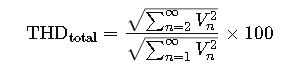
Used primarily in signal processing. For power systems, the denominator is often just V₁ or I₁.
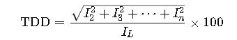
3. Total Demand Distortion (TDD)
IEEE 519 introduces TDD for current-based harmonics:
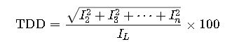
- I<sub>L</sub> is the maximum fundamental load current demand measured over 15 or 30 min.
In-Depth Explanation of THD Formulas and Variables
Understanding how each variable contributes to the Total Harmonic Distortion (THD) is essential for both accurate analysis and compliance with standards such as IEEE 519-2022, IEC 61000-4-7, and IEC 61000-2-4.
A. Breakdown of Key Variables
| Symbol | Description |
|---|---|
| V<sub>1</sub> | RMS voltage of the fundamental frequency (typically 50 Hz or 60 Hz) |
| V<sub>n</sub> | RMS voltage of the nth harmonic (n = 2, 3, 4, …) |
| I<sub>1</sub> | RMS current of the fundamental frequency |
| I<sub>n</sub> | RMS current of the nth harmonic |
| n | Harmonic order, where n = 2 (2nd harmonic), n = 3 (3rd), up to 50 or higher |
| I<sub>L</sub> | Maximum demand load current at fundamental frequency (IEEE 519) |
| I<sub>SC</sub> | Short-circuit current at the point of common coupling (PCC) |
B. Explanation of Each Formula
1. THD (Voltage or Current)
This is the most used formula in field instruments and power quality analyzers:
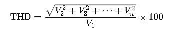
- Interpretation: This shows how much distortion is present compared to the clean sine wave component.
- Measurement: Requires a harmonics analyzer capable of isolating harmonic components.
- Example value: If V<sub>1</sub> = 230 V and the RMS sum of all harmonic voltages is 23 V, THD = 10%.
2. THD Including Fundamental (Signal Processing Context)

- Used less frequently in power engineering but common in signal integrity applications.
3. TDD (Total Demand Distortion)
- Why use it? Because THD alone is misleading when load is small. TDD compares distortion to full-load capacity.
- Compliance context: All TDD values must meet IEEE 519 thresholds depending on the I<sub>SC</sub>/I<sub>L</sub> ratio at PCC.
Real-World Examples of THD Calculation and Application
To solidify the understanding of these formulas, here are two detailed real-world engineering applications.
Example 1: THD in a Data Center with VFD Loads
Scenario:
A 480 V three-phase data center uses several Variable Frequency Drives (VFDs) and LED lighting. An engineer is tasked with measuring voltage THD at the main distribution board.
Measured Harmonic Voltages (RMS):
| Harmonic Order (n) | Voltage (V<sub>n</sub>) |
|---|---|
| Fundamental (V₁) | 480.0 V |
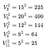
| 3rd | 15.0 V |
| 5th | 20.0 V |
| 7th | 12.0 V |
| 9th | 8.0 V |
| 11th | 5.0 V |
Step-by-Step Calculation:
- Square each harmonic:
- Sum of squares:

- Calculate THD:
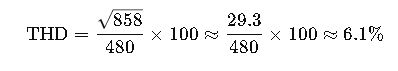
Interpretation:
- This THD level exceeds the IEEE 519 limit of 5% for voltages <1 kV.
- Suggests the need for harmonic filters or load balancing.
Example 2: TDD Compliance for an Industrial Motor System
Scenario:
An industrial plant with a 400 kW VFD-controlled motor is supplied from a 13.8 kV bus. The short-circuit current (I<sub>SC</sub>) at the PCC is 10,000 A. The max fundamental load current I<sub>L</sub> is 900 A.
Measured Current Harmonics:
| Harmonic Order (n) | Current (I<sub>n</sub>) |
|---|---|
| 5th | 300 A |
| 7th | 150 A |
| 11th | 90 A |
| 13th | 60 A |
Step-by-Step Calculation:
- Square and sum harmonics:

- RMS sum of harmonics:

- TDD:

- Calculate I<sub>SC</sub>/I<sub>L</sub>:
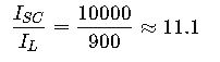
- IEEE 519 Limit (from Table 2): For I<sub>SC</sub>/I<sub>L</sub> < 20 → Limit = 5%
Conclusion:
- TDD = 39.2% >> 5% — this is a serious violation.
- Mitigation required: detuned harmonic filters or multi-pulse drives.
Regulatory Context and Mitigation Strategies
Maintaining THD and TDD within acceptable limits is required by numerous standards:
Key Standards
| Standard | Focus | Max THD/TDD (%) |
|---|---|---|
| IEEE 519-2022 | Harmonic limits at PCC | 5% Voltage / 5–20% TDD |
| IEC 61000-2-4:2017 | Harmonics in industrial environments | Class 1–3: 5–10% |
| IEC 61000-4-7:2021 | Measurement methodology for harmonics | — |
Mitigation Methods
- Passive Filters
- Tuned L-C circuits absorb specific harmonic orders.
- Cost-effective, but limited to fixed frequency loads.
- Active Harmonic Filters
- Power-electronic based; cancel a wide range of harmonics dynamically.
- Ideal for variable loads and multiple harmonics.
- Multi-Pulse Converters (12-pulse, 18-pulse)
- Use phase-shifting transformers to cancel harmonics.
- Effective for large VFDs and UPS.
- K-Rated Transformers
- Designed to handle high harmonic currents without overheating.
- Used in commercial and industrial installations.