Emergency lighting ensures safe evacuation during power outages, protecting occupants and complying with building safety codes. The NEC, NFPA 101, and UL 924 provide detailed standards for designing emergency lighting systems.
Emergency Lighting Load Calculator (NEC)
What power factor should I use if unknown?
Which voltage to select (L–N vs L–L)?
Formulas used
Three Phase (L–L): I = W / (√3·V·PF).
DC: I = W / V.
Common Values for Emergency Lighting Calculation
The following table summarizes the typical values used in emergency lighting calculations, based on NEC and NFPA standards:
| Parameter | Value | Unit | Source/Reference |
|---|---|---|---|
| Minimum Illumination (Path of Egress) | 1.0 (average) / 0.1 (minimum) | foot-candles (fc) | NEC, NFPA 101 |
| Illumination After 90 Minutes | 0.6 (average) / 0.06 (minimum) | foot-candles (fc) | NEC, NFPA 101 |
| Maximum-to-Minimum Illumination Ratio | 40:1 | – | NEC, NFPA 101 |
| Minimum Duration of Illumination | 90 | minutes | NEC, NFPA 101 |
| Automatic Transfer Time | 10 | seconds | NEC, UL 924 |
| Emergency Lighting Load (General) | 1/3 | VA/sq.ft. | Industry Practice forums.mikeholt.com |
| Emergency Lighting Load (Healthcare) | 1/3 | VA/sq.ft. | Industry Practice forums.mikeholt.com |
| Generator Sizing Load | 1/3 | VA/sq.ft. | Industry Practice forums.mikeholt.com |
Formulas for Emergency Lighting Calculation
1. Illumination Level Calculation
To determine the illumination level at a specific point along the egress path:
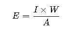
Where:
- E= Illumination level at the point (fc)
- I= Luminous output of the emergency luminaire (lumens)
- W= Wattage of the emergency luminaire (watts)
- A= Area illuminated by the luminaire (square feet)
2. Emergency Lighting Load Calculation
For general lighting areas:
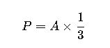
Where:
- P= Emergency lighting load (VA)
- A= Area of the space (square feet)
For healthcare facilities, the load calculation remains the same.
3. Generator Sizing for Emergency Lighting
To estimate the generator size required for emergency lighting:
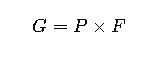
Where:
- G= Generator size (kVA)
- P= Emergency lighting load (kVA)
- F= Safety factor (typically 1.25 to 1.5)
Real-World Application Examples
Example 1: Office Building
Scenario: An office building with a total area of 10,000 sq.ft. requires emergency lighting.
Calculation:
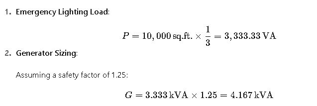
Conclusion: A generator with a capacity of at least 4.2 kVA is recommended to support the emergency lighting system.
Example 2: Healthcare Facility
Scenario: A hospital with an area of 20,000 sq.ft. needs emergency lighting.
Calculation:
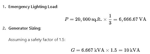
Conclusion: A generator with a capacity of at least 10 kVA is recommended to support the emergency lighting system in the healthcare facility.
Key Factors in Emergency Lighting Design
Compliance with NEC Requirements
Emergency lighting systems are regulated under NEC Article 700, which covers “Emergency Systems”. These requirements ensure that lighting systems provide safe egress during power outages. Critical elements include:
- Power Source: Emergency systems must be connected to a reliable secondary power source, often a generator or battery-based system.
- Automatic Transfer: The transition from normal to emergency power should occur automatically, typically within 10 seconds, to prevent hazardous dark conditions.
- Load Prioritization: Systems should supply essential areas first, such as exit routes, fire alarms, and critical equipment in healthcare or industrial facilities.
Illumination Levels and Uniformity
Proper illumination is vital for safety. NEC and NFPA guidelines define minimum and average foot-candle levels:
- Path of Egress: Minimum 0.1 foot-candles, average 1.0 foot-candle.
- Stairs and Corridors: Adequate illumination to prevent falls and allow easy evacuation.
- Maximum-to-Minimum Ratio: Should not exceed 40:1 to avoid overly bright or dark spots, ensuring a uniform light distribution.
Lighting design should consider the reflectivity of surfaces (walls, floors, ceilings), as this can significantly influence the required output of luminaires to achieve code-compliant lighting.
Types of Emergency Lighting
- Central Battery Systems
- Provide power to multiple luminaires from a centralized battery bank.
- Useful in large commercial or industrial facilities.
- Easier maintenance as the batteries are centralized, and inspection is simplified.
- Self-Contained Units
- Each luminaire has its own integrated battery.
- Ideal for smaller buildings, retrofits, or areas with low power demand.
- Can include LED or fluorescent technology.
- Generator-Backed Systems
- Suitable for healthcare, industrial plants, or critical operations requiring extended emergency operation.
- Can supply both lighting and essential equipment.
- Hybrid Systems
- Combine central battery and generator support for maximum reliability.
Real-World Applications and Considerations
Office Buildings
In commercial offices, emergency lighting primarily serves evacuation routes and stairways. Designers often implement self-contained LED units due to lower energy consumption and simplified installation.
Additional considerations include:
- Occupancy Patterns: Areas with higher daytime occupancy may require more luminaires to maintain illumination levels if power loss occurs during business hours.
- Maintenance Accessibility: Units should be easy to access for periodic testing and battery replacement.
Healthcare Facilities
Hospitals and clinics have strict emergency lighting requirements due to critical life safety needs:
- Patient Rooms: Must maintain safe illumination for evacuation or medical procedures.
- Operating Rooms and ICUs: Typically powered by both generator and central battery systems to ensure zero downtime.
- Corridors and Stairwells: Strategically placed luminaires ensure clear visibility and adherence to NFPA 101 Life Safety Code.
Healthcare systems must undergo frequent inspection and testing, including monthly operational checks and annual full-load testing of batteries and generators.
Advanced Considerations
Integration with Fire Alarm Systems
Emergency lighting systems often integrate with fire alarm panels. When an alarm is triggered:
- Luminaires automatically switch to emergency mode.
- Flashing or color-coded lighting can guide occupants toward exits in smoke-filled environments.
Energy Efficiency
Modern emergency lighting uses LED technology, offering:
- Lower power consumption, allowing smaller battery or generator capacity.
- Longer lifespan, reducing maintenance costs.
- Dimmable operation, ensuring compliance with illumination standards while conserving energy.
Testing and Compliance
NEC requires periodic testing of emergency lighting:
- Monthly: Short-duration test to ensure each luminaire illuminates properly.
- Annually: Full-duration test to confirm batteries or generator can sustain illumination for at least 90 minutes.
Failure to comply can result in code violations, reduced insurance coverage, and increased safety risks.
Practical Design Strategies
- Zoning: Divide large buildings into zones for more efficient emergency lighting distribution.
- Redundancy: Include additional luminaires in critical areas to account for failures or maintenance downtime.
- Reflective Materials: Use high-reflectivity paint or flooring to reduce the number of luminaires required while maintaining illumination levels.
- Simulation and Modeling: Utilize lighting design software to model illumination levels and egress visibility before installation.