Designing an efficient cable tray system is essential to ensure safe, reliable electrical installation operation.
Proper tray sizing based on cable capacity prevents overheating, physical damage, and allows future system expansion.
Cable Tray Sizing Calculator (Capacity-Based)
| # | Description | OD (mm) | Qty | Area each | Total area | |
|---|---|---|---|---|---|---|
| Sum of cable areas: | — | |||||
What fill factor should I use?
Formulas used
Required usable tray area: Ausable ≥ ΣAc / Fill.
Suggested sizes (check): Fill% = ΣAc / (W·H·Fill) × 100 (W = interior width, H = side height).
Limitations
Common Cable Tray Sizing Values
The following tables present standard cable tray sizes and their corresponding capacities, commonly used in industrial and commercial installations
Table 1: Common Cable Tray Widths and Load Capacities
| Tray Width (mm) | Load Capacity (kg/m) | Suitable Cable Types |
|---|---|---|
| 100 | 75 | Small power and control cables |
| 150 | 100 | Medium-sized power cables |
| 200 | 125 | Large power cables and multiple runs |
| 300 | 150 | High-density installations |
| 600 | 200 | Heavy-duty applications |
Table 2: Cable Fill Percentages for Different Tray Types
| Tray Type | Maximum Fill Percentage | Notes |
|---|---|---|
| Ladder | 50% | Suitable for large cables with sufficient spacing |
| Perforated | 40% | Allows for better ventilation |
| Solid | 30% | Limited airflow; used for specific applications |
Formulas for Cable Tray Sizing Based on Cable Capacity
To determine the appropriate cable tray size, several factors must be considered, including the total cross-sectional area of the cables, the fill factor, and the tray’s dimensions.
1. Total Cable Cross-Sectional Area (TCSA)
The TCSA is calculated by summing the cross-sectional areas of all cables to be installed in the tray
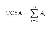
Where:
- Ai= Cross-sectional area of the iii-th cable (mm²)
- n= Total number of cables
2. Tray Area Required (TAR)
The TAR is determined by dividing the TCSA by the fill factor (FF), which accounts for the desired percentage of tray occupancy:
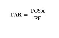
Where:
- FF= Fill factor (expressed as a decimal; e.g., 0.5 for 50%)
3. Tray Dimensions
To find the required tray width (W) and height (H), the following relationships are used:

The dimensions should be selected based on standard tray sizes and the calculated TAR.
Real-World Examples
Example 1: Sizing for a Medium-Voltage Power Distribution System
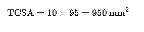
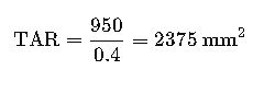
In a medium-voltage power distribution system, 10 cables of 95 mm² cross-sectional area each are to be installed in a ladder tray. The desired fill factor is 40%.
- Calculate TCSA:
- Determine TAR:
- Select Tray Dimensions:
Assuming a standard tray height of 100 mm, calculate the required width:
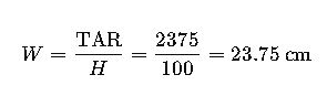
Therefore, a 300 mm wide tray would be suitable.
Example 2: High-Density Data Center Installation
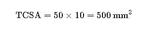
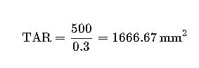
In a data center, 50 cables of 10 mm² cross-sectional area each are to be installed in a perforated tray. The desired fill factor is 30%.
- Calculate TCSA:
- Determine TAR:
- Select Tray Dimensions:
Assuming a standard tray height of 50 mm, calculate the required width:
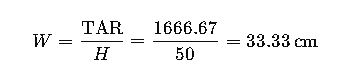
Therefore, a 400 mm wide tray would be suitable.
Additional Considerations
- Future Expansion: Always include a margin (typically 20-25%) for future cable additions.
- Environmental Factors: Consider ambient temperature, humidity, and potential chemical exposure, as these can affect cable performance and tray material selection.
- Cable Arrangement: Ensure that cables are arranged in a single layer with adequate spacing to allow for heat dissipation and easy maintenance.
- Compliance with Standards: Adhere to relevant standards such as IEC 61537 and IEC 60287 for cable tray design and cable sizing.
Conclusion
Proper cable tray sizing is essential for the safety, efficiency, and scalability of electrical installations. By meticulously calculating the total cable cross-sectional area, selecting appropriate tray dimensions, and considering future needs and environmental factors, engineers can design cable tray systems that meet current requirements and accommodate future growth.
For further reading and detailed guidelines, refer to the following resources: