Designing photovoltaic systems compliant with NEC and IEC standards requires precise cable sizing for safety. Conductor area, insulation type, current capacity, and voltage drop determine efficiency and long-term system reliability.
Cables for Photovoltaic Systems Calculator — NEC & IEC
Calculate PV string current, design ampacity, voltage drop and suggested conductor sizes (mm² / AWG). Use results as engineering guidance — verify with local code.
How this calculator works (formulas)
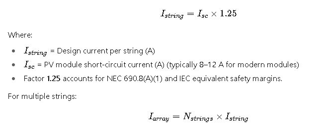
- If Isc is provided the tool uses Design current = Isc × multiplier (default 1.25). Otherwise it computes string current from power: I = Power_of_string / V_string.
- Total array current = design current × number of parallel strings.
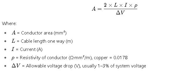
- Voltage drop (single conductor round-trip) uses conductor resistivity (Ω·mm²/m): copper 0.017241, aluminium 0.0282. V_drop = I × (2 × length) × (resistivity / A_mm2).
- Suggested conductor sizes are matched to a conservative ampacity table embedded in the tool. Always confirm with local code.
Key Considerations in PV Cable Selection
When calculating cables for PV systems, the following engineering parameters are critical:
- Maximum Current (Imax): Determined by PV module short-circuit current (Isc) and stringing configuration.
- Conductor Cross-Sectional Area (A): Ensures thermal, mechanical, and electrical performance.
- Voltage Drop (ΔV): Limited by codes, typically ≤3% for DC strings and ≤1.5–2% for AC feeders.
- Temperature Correction Factors: Adjust ampacity according to ambient temperature, sunlight exposure, and installation method.
- Conductor Material: Copper vs. aluminum, with different conductivity, cost, and weight implications.
- Insulation Type: PV-specific cables such as PV1-F (IEC) or USE-2, RHW-2 (NEC) with UV and ozone resistance.
- Standards Compliance: NEC Article 690, 310, 705 and IEC 60364-5-52, IEC 62930 for PV cable requirements.
Extended Reference Tables for PV Cable Sizing
The following tables summarize common cable cross-sections, ampacity values, and voltage drop reference data under NEC and IEC guidelines. These values are typical and should be adjusted using correction factors from the standards.
Table 1 – Common PV Cable Sizes and Ampacities (Copper, 90 °C Insulation, Single-Core in Conduit, IEC & NEC Reference)
| Conductor Area (mm²) | Equivalent AWG | Ampacity (A) NEC | Ampacity (A) IEC | Typical Use in PV Systems |
|---|---|---|---|---|
| 2.5 mm² | 14 AWG | 25 A | 24 A | Single string, small arrays |
| 4 mm² | 12 AWG | 30 A | 32 A | 2–3 strings combined |
| 6 mm² | 10 AWG | 40 A | 38 A | Larger string groups |
| 10 mm² | 8 AWG | 55 A | 52 A | Array output to combiner |
| 16 mm² | 6 AWG | 75 A | 68 A | Combiner to inverter DC |
| 25 mm² | 4 AWG | 95 A | 89 A | Inverter DC busbars |
| 35 mm² | 2 AWG | 115 A | 109 A | Inverter–switchgear |
| 50 mm² | 1 AWG | 150 A | 135 A | Large utility PV |
| 70 mm² | 2/0 AWG | 195 A | 171 A | Central inverter feeders |
| 95 mm² | 3/0 AWG | 225 A | 202 A | Medium-voltage step-up |
| 120 mm² | 4/0 AWG | 260 A | 230 A | High-capacity feeders |
| 150 mm² | 300 kcmil | 285 A | 255 A | Utility-scale PV |
| 240 mm² | 500 kcmil | 380 A | 340 A | Substation tie cables |
Table 2 – Typical Voltage Drop per 100 m (DC, Copper, 90 °C, Resistivity ρ = 0.0178 Ω·mm²/m)
| Conductor Area (mm²) | Resistance (Ω/km) | Voltage Drop at 20 A (V/100 m) | Voltage Drop at 50 A (V/100 m) | Voltage Drop % at 1000 V DC |
|---|---|---|---|---|
| 2.5 mm² | 7.41 | 14.82 V | 37.05 V | 1.48% – 3.7% |
| 4 mm² | 4.61 | 9.22 V | 23.05 V | 0.92% – 2.3% |
| 6 mm² | 3.08 | 6.16 V | 15.40 V | 0.62% – 1.54% |
| 10 mm² | 1.83 | 3.66 V | 9.15 V | 0.37% – 0.91% |
| 16 mm² | 1.15 | 2.30 V | 5.75 V | 0.23% – 0.58% |
| 25 mm² | 0.73 | 1.46 V | 3.65 V | 0.15% – 0.36% |
| 35 mm² | 0.52 | 1.04 V | 2.60 V | 0.10% – 0.26% |
| 50 mm² | 0.36 | 0.72 V | 1.80 V | 0.07% – 0.18% |
| 70 mm² | 0.26 | 0.52 V | 1.30 V | 0.05% – 0.13% |
Core Formulas for PV Cable Sizing (NEC & IEC)
Cable sizing relies on applying standard electrical engineering formulas in line with NEC/IEC. Below are the most critical formulas and their detailed explanations.
1. Maximum Current Calculation
2. Conductor Cross-Sectional Area from Voltage Drop
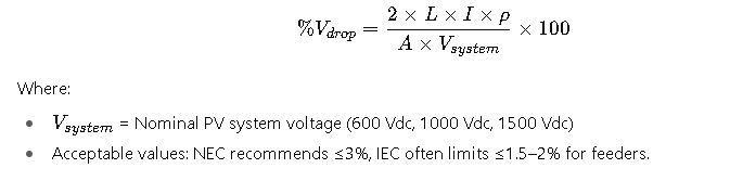
3. Voltage Drop Percentage
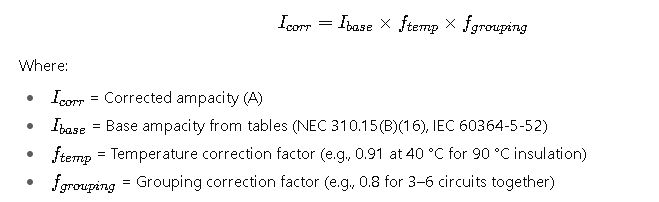
4. Corrected Ampacity (NEC / IEC)
Detailed Explanation of Key Variables in PV Cable Sizing
When applying the NEC or IEC standards in cable sizing, every variable has a defined meaning and practical range. Understanding them is critical for accurate and compliant results.
1. Current Values (Isc, Istring, Iarray)
- Short-Circuit Current (Isc): Provided by the PV module datasheet, usually between 8 A and 12 A for modern 400–600 W panels. This is the basis for current sizing.
- String Current (Istring): Equivalent to Isc with a 25% safety factor. A typical residential string might operate at 9–12 A nominal but must be sized for 12–15 A.
- Array Current (Iarray): Depends on the number of parallel strings. For example, 8 strings each at 12 A require conductors capable of at least 96 A, corrected by factors.
2. Cable Length (L)
- Length refers to the one-way distance between PV modules, combiners, and inverters.
- Longer runs increase resistance and losses. For rooftop arrays, lengths range between 10–50 m. Utility-scale ground-mounted systems often reach 100–250 m per string.
3. System Voltage (Vsystem)
- Residential and small commercial systems often operate at 600 V DC.
- Large commercial and utility-scale systems typically operate at 1000 V DC or 1500 V DC.
- Higher voltages reduce current for the same power, allowing smaller cable sizes.
4. Conductor Material
- Copper: Higher conductivity, lower resistance, smaller cross-sectional area, higher cost.
- Aluminum: Lower conductivity, larger cross-sectional area needed, lighter and cheaper for long runs. Often used in utility-scale feeders.
5. Conductor Area (A)
- Expressed in square millimeters (IEC) or American Wire Gauge (AWG, NEC).
- Typical residential PV uses 4–10 mm² (12–8 AWG).
- Utility feeders may require 70–240 mm² (2/0 AWG to 500 kcmil).
6. Voltage Drop (ΔV)
- Both NEC and IEC recommend minimizing voltage drop for efficiency.
- Common design limits: ≤1.5% for DC strings, ≤3% for total DC runs, ≤2% for AC feeders.
- Lower voltage drop increases system efficiency and reduces heating losses.
7. Temperature Correction Factor
- Cable ampacity is reduced in high ambient temperatures.
- At 40 °C, ampacity may be reduced by 10%. At 50 °C, derating may exceed 20%.
- PV cables on rooftops or in conduits exposed to sunlight often experience 50–60 °C, making correction factors essential.
8. Grouping Correction Factor
- Multiple cables installed together reduce heat dissipation.
- If 4–6 current-carrying conductors share a conduit, ampacity must be reduced by 20–30%.
- This is critical in central inverter designs where dozens of strings converge.
NEC vs. IEC Approaches in PV Cable Sizing
Both NEC and IEC provide rigorous frameworks, but their philosophies differ slightly.
NEC (National Electrical Code – United States, NFPA 70)
- Focus on safety and worst-case conditions.
- Requires multiplying PV module short-circuit current by 125% twice: once for continuous current and once for conductor sizing.
- Strong emphasis on conductor ampacity tables (Article 310) and derating for environment.
- Insulation types commonly used: USE-2, RHW-2, THWN-2, PV wire.
- Clear requirements for overcurrent protection, disconnecting means, and rapid shutdown.
IEC (International Electrotechnical Commission – Europe, Asia, International)
- Focus on efficiency and practical limits.
- Typically applies a single 1.25 multiplier to Isc for conductor sizing.
- Voltage drop limitations are stricter, usually ≤1.5% for feeders.
- Widely uses PV1-F cables (EN 50618, IEC 62930), optimized for UV, weather, and mechanical resistance.
- Grouping and temperature corrections are applied from IEC 60364-5-52 tables.
Key takeaway: NEC tends to result in larger, more conservative conductor sizes compared to IEC, but IEC emphasizes minimizing voltage drop more strictly.
Real-World Case Study 1: Residential Rooftop PV System
Scenario:
- A 10 kW residential PV installation with 25 modules (400 W each).
- Each module: Isc = 10 A, Voc = 40 V.
- Strings: 5 strings × 5 modules in series (200 V string voltage).
- Inverter: 10 kW single-phase, 600 V DC input.
- Cable length: 25 m one-way (50 m round trip).
- Location: Arizona, USA (ambient up to 45 °C).
Step-by-Step Process:
- Determine Current: Each string carries about 10 A × 1.25 = 12.5 A. With 5 parallel strings, total current = 62.5 A.
- Select Conductor Size (Ampacity):
- From NEC tables, 6 AWG (13.3 mm²) copper has ~65 A ampacity at 90 °C.
- Apply temperature correction (0.87 at 45 °C): 65 A × 0.87 = 56.5 A (too low).
- Move to 4 AWG (21 mm²) copper, corrected ampacity = 76 A (acceptable).
- Check Voltage Drop: For 50 m run, 4 AWG gives <2% voltage drop at 62.5 A, within NEC recommendations.
- Final Selection: 4 AWG copper PV wire, UV-resistant, rated 90 °C wet.
Result:
The system complies with NEC requirements, maintaining safe ampacity and acceptable voltage drop even under high-temperature conditions.
