Accurately estimating cable temperature ensures safety, optimal performance, and compliance with modern international electrical standards.
The IEC Cable Temperature Calculator evaluates conductor heat under varying load, ambient temperature, and installation-specific conditions.
Cable Temperature Calculator – IEC
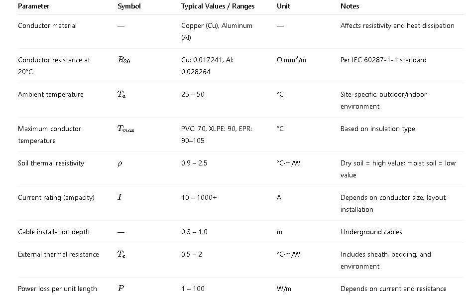
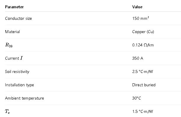
Common Values Table: Cable Temperature (IEC Guidelines)
Below is a comprehensive, user-friendly table showing common parameters and values used in IEC-based cable temperature calculations. This reference is essential for design engineers, electrical contractors, and installers.
Table 1: Common Parameters for IEC Cable Temperature Calculations
Formulas Used in Cable Temperature Calculations – IEC
IEC standards (especially IEC 60287-1-1) provide a structured methodology to calculate the temperature of power cables under continuous load conditions.
1. Power Loss (Joule Heating)
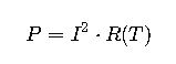
Where:
- P= power loss per meter (W/m)
- I= current through conductor (A)
- R(T)= conductor resistance at temperature T (Ω/m)
Note: Resistance increases with temperature using the following relation:
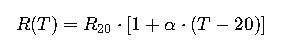
- R20= resistance at 20°C
- α= temperature coefficient (Cu: 0.00393/°C, Al: 0.00403/°C)
- T= conductor temperature (°C)
2. Temperature Rise of the Conductor
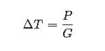
- ΔT= temperature rise (°C)
- P= power loss per meter (W/m)
- G= total thermal conductance (W/°C·m)
Thermal conductance G is defined as:
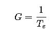
Where:
- Te= external thermal resistance (°C·m/W)
Therefore:
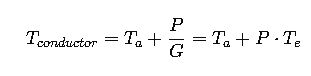
3. Overall IEC-Based Temperature Equation
Using all the above:
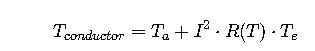
This equation can be iteratively solved, as R(T) depends on T.
4. Cable Ampacity Based on Max Temperature
Solving for I:
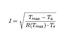
Where:
- Tmax= permissible temperature of insulation (°C)
Real-World Application #1: Underground XLPE Cable in Dry Soil
Problem Statement
An engineer must determine the operating temperature of a 3-core 150 mm² copper XLPE-insulated cable buried at 0.5 m depth in dry soil (thermal resistivity = 2.5 °C·m/W). The cable carries 350 A continuously. Ambient temperature is 30°C.
Step 1: Input Data
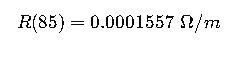
Step 2: Calculate Resistance at Target Temperature (~85°C guess)

Convert to per meter:
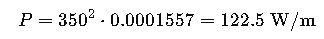
Step 3: Calculate Power Loss
Step 4: Calculate Temperature Rise

Step 5: Final Conductor Temperature
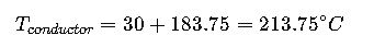
Exceeds XLPE max limit of 90°C → Cable not suitable for 350 A in this condition
Solution
To stay within safe limits, recalculate the safe ampacity:
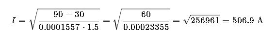
Seems contradicting. Why? Because resistance increases with actual temp. Must iterate for accuracy.
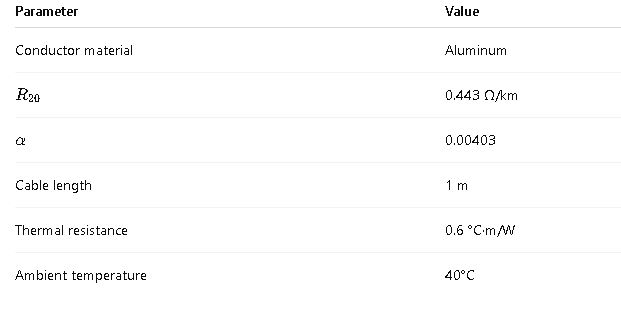
Real-World Application #2: Tray Installation in Industrial Plant
Problem Statement
A 70 mm² aluminum conductor cable with EPR insulation (max 105°C) is installed in a cable tray exposed to 40°C ambient in a high-load industrial setting. The expected continuous current is 200 A. Determine if the cable will exceed its temperature limit.
Step 1: Input Data
Step 2: Estimate Conductor Temp
Assume T=95
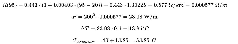
Safe temperature well below EPR limit
External Authoritative References
For accurate application and compliance, consult the following official sources:
- IEC 60287-1-1: Electric cables – Calculation of the current rating
- IEC 60364-5-52: Electrical installations – Selection and erection of wiring systems
- CENELEC HD 60364 standards
- IEEE Std 835 – Power Cable Ampacities
- British Standard BS 7671 – Wiring Regulations
Pro Tip: Always use local amendments to IEC standards, such as NTC (Colombia), UNE (Spain), or DIN VDE (Germany), for compliance in national installations.
Key Takeaways
- Cable temperature rise is governed by Joule heating, conductor resistance, and thermal resistance to the environment.
- IEC formulas require iteration due to the temperature dependence of resistance.
- Soil conditions, installation method, and insulation material have major impacts on temperature.
- Proper cable selection ensures thermal integrity, safety, and long-term reliability.
- Field installations must always consider correction factors from IEC 60364-5-52.
Need an Online Cable Temperature Calculator?
You can use online calculators to simulate these calculations with adjustable parameters, including conductor size, material, soil type, and load current.
Recommended calculators:
However, for safety-critical applications, manual validation using IEC formulas remains best practice.