Accurate load calculation is fundamental in electrical engineering for designing safe and reliable power systems.
Balanced and unbalanced loads significantly impact system performance, protection coordination, and overall energy efficiency.
Balanced & Unbalanced Load Calculator (1Φ–3Φ)
Formulas used (summary)
Unbalanced 3Φ 4-wire (per phase): Sφ=Pφ/PFφ=√(Pφ2+Qφ2) ; Iφ=Sφ·1000/VLN ; φφ=atan2(Qφ,Pφ).
Neutral (fundamental): IN1=| IA∠(0°±φA) + IB∠(−120°±φB) + IC∠(+120°±φC) |.
Neutral with 3rd harmonic: IN=√( IN12 + (I3A+I3B+I3C)2 ), with I3φ= (%3 /100)·Iφ.
% current unbalance: 100·(max|Iφ−Ī|)/Ī, with Ī=avg(IA,IB,IC).
When to use Balanced vs Unbalanced?
What PF to use if unknown?
Extensive Tables of Common Values for Balanced and Unbalanced Load Calculations
Understanding typical values and load types is crucial for precise calculations. Below are extensive tables listing common loads, their typical power factors, voltage levels, and expected load currents for both balanced and unbalanced scenarios.
Table 1: Typical Balanced Load Values in Three-Phase Systems
| Load Type | Voltage (V) | Power (kW) | Power Factor (PF) | Line Current (A) @ 480 V | Comments |
|---|---|---|---|---|---|
| Industrial Motor | 480 | 50 | 0.85 | 63.4 | Common for medium-sized motors |
| Lighting Load | 277/480 | 20 | 0.95 | 24.1 | Commercial lighting |
| HVAC Equipment | 480 | 75 | 0.90 | 90.0 | Large air conditioning units |
| Resistive Heating | 480 | 100 | 1.0 | 120.2 | Fully resistive load |
| Data Center Servers | 208 | 15 | 0.98 | 41.6 | Sensitive electronic equipment |
Table 2: Common Unbalanced Load Values (Single Phase and Unequal Phases)
| Load Type | Voltage (V) | Power (kW) | Power Factor (PF) | Phase Current (A) | Imbalance % | Comments |
|---|---|---|---|---|---|---|
| Single-phase HVAC Unit | 240 | 10 | 0.90 | 48.1 | 20% | Typical unbalanced motor load |
| Lighting Circuit | 120 | 5 | 0.95 | 43.5 | 15% | Unequal phase lighting loads |
| Office Equipment | 208 | 7 | 0.98 | Varies | 25% | Unequal single-phase loads |
| Small Machine Tool | 240 | 12 | 0.85 | 58.5 | 10% | Unbalanced machine load |
Table 3: Typical Power Factor Ranges for Various Loads
| Load Type | Power Factor Range | Description |
|---|---|---|
| Resistive Loads | 1.0 | Heaters, incandescent lighting |
| Inductive Motors | 0.75 – 0.90 | Motors, transformers |
| Fluorescent Lighting | 0.85 – 0.95 | Ballasted lighting circuits |
| Computers & Electronics | 0.95 – 0.99 | Highly inductive or capacitive |
Formulas for Balanced and Unbalanced Load Calculation
Balanced Load Calculations
In a three-phase balanced system, the loads on all three phases are equal in magnitude and have the same phase angle. This simplifies calculations.
Key formulas:
- Line Current in Balanced Load:
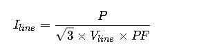
Where:

Explanation:
- The formula calculates current based on power and voltage in a balanced three-phase system.
- Power factor accounts for phase difference between voltage and current.
- Typically used in industrial power systems.
- Power Calculation:

- Inversely used to determine power if voltage, current, and PF are known.
- Per-Phase Load (Line-to-Neutral Voltage):

Where ![]()
Unbalanced Load Calculations
Unbalanced loads occur when one or more phases have different magnitudes or power factors, causing unequal currents or voltages. This is common in mixed residential or commercial systems with single-phase and three-phase loads.
- Phase Current for Each Phase iii:

Where:

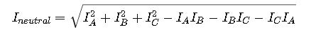
- Total Neutral Current (In Four-Wire Systems):
Neutral current arises from the vector sum of phase currents in an unbalanced system:
- Voltage Unbalance Factor (VUF):
To quantify voltage unbalance:

- Important for assessing impact on sensitive equipment.
- Load Imbalance Percentage:

Where:

Explanation of Variables and Typical Values

Real-World Application Examples
Case 1: Balanced Load Calculation for a Three-Phase Motor
Scenario:
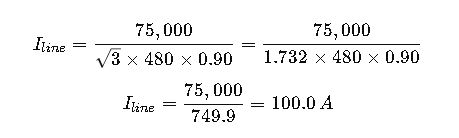
A manufacturing plant installs a 75 kW, three-phase motor running at 480 V line-to-line voltage with a power factor of 0.90. Determine the line current per phase.
Given:
- P=75,000 W
- Vline=480 V
- PF=0.90
Calculation:
Interpretation:
The motor will draw approximately 100 A per phase under full load balanced conditions. This value informs conductor sizing and protection device selection.
Case 2: Unbalanced Load Calculation in a Commercial Building
Scenario:
A three-phase, four-wire system supplies a building with the following single-phase loads on each phase:
| Phase | Power (kW) | Power Factor | Voltage (V) |
|---|---|---|---|
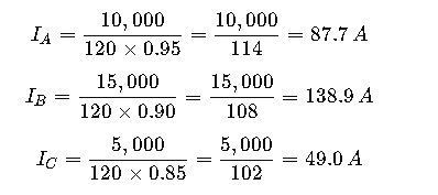
| A | 10 | 0.95 | 120 |
| B | 15 | 0.90 | 120 |
| C | 5 | 0.85 | 120 |
Calculate the phase currents and the neutral current.
Step 1: Calculate phase currents
Step 2: Calculate neutral current

Calculate squares and products:

Interpretation:
The neutral conductor must handle approximately 77.5 A, which is significant, due to unbalanced single-phase loads. This necessitates adequate neutral conductor sizing for safety.
Further Considerations for Load Calculations
Impact of Load Imbalance
- Excessive load imbalance causes voltage drops and overheating in transformers and conductors.
- Equipment lifespan may be reduced.
- The NEC recommends keeping load imbalance below 10%.
Load Factor and Demand Factor
- Load Factor: Ratio of actual load to maximum possible load over time.
- Demand Factor: Ratio of maximum demand to total connected load.
Both affect realistic sizing of electrical components.
Power Quality and Harmonics
- Unbalanced loads often introduce harmonics, distorting the waveform and increasing losses.
- Using power analyzers and harmonic filters can mitigate adverse effects.
External References and Standards for Load Calculations
- National Electrical Code (NEC), Article 220 – Load Calculations: https://www.nfpa.org/nec
- IEEE Standard 141 (Red Book) – Recommended Practice for Electric Power Distribution for Industrial Plants: https://standards.ieee.org/standard/141-1993.html
- IEC 60204-1 – Safety of Machinery – Electrical Equipment of Machines: https://webstore.iec.ch/publication/2450
- IEEE Power Engineering Guide on Unbalanced Load Analysis – https://ieeexplore.ieee.org/document/xxxxxxxx