Instant current-limiting fuses control fault energy to protect equipment and limit downstream failures quickly reliably.
This article quantifies let-through, compares screen fault current impact and fuse class selection with precision.
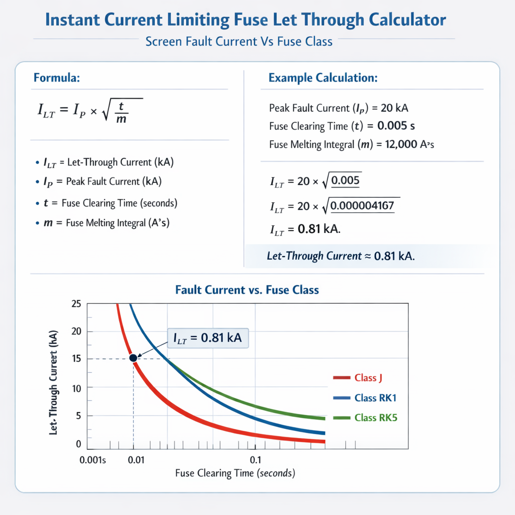
Instant Current-Limiting Fuse Let-Through — Compare Prospective Fault Current vs Fuse Class
Operational principles of instant current-limiting fuses
Instant current-limiting fuses interrupt short-circuit currents before the upstream source can reach its prospective steady-state value. They operate by melting one or more fusible elements rapidly and extinguishing the arc within the fuse body; the resulting peak let-through current and I2t energy are therefore a function of fuse design, time-current behavior, and the network impedance ahead of the fuse.Key behaviors distinguishing current-limiting fuses:- Fast melt and clearing times at high overcurrents, producing substantially reduced prospective peak current (Ipeak,lt).
- Defined let-through energy quantified as I2t (integral of squared current over time), which is used for thermal comparisons with downstream equipment capability.
- Time-current (TCC) curves and let-through curves provided by manufacturers—use these curves for accurate engineering selection rather than approximate formulas alone.
Defining screen fault current and its engineering implications
What is a screen fault current?
In cable systems a "screen fault" (or fault to cable screen/armor/earth) occurs when a conductor contacts the cable screen or metallic sheath, producing a fault path that often has different impedance than a phase-to-phase short. In power systems context, "screen fault current" can be generalized as any fault type where the fault path impedance and resultant asymmetry affect the time-current outcome and the effectiveness of a fuse class in limiting energy.Engineering implications:- The fault path impedance Zf (including screen, armor, or soil-return path) alters the prospective fault current magnitude.
- Different fault currents (phase-to-phase, phase-to-earth, screen) can produce different melting/clearing times for the same fuse.
- Fuse class selection must account for the lowest impedance fault scenario that the fuse will need to clear, and for equipment that may fail due to high I2t even for short-duration faults.
Key formulas and variable definitions
All formulas are presented using standard HTML notation. Each variable is explained and typical ranges are provided for engineering use.Prospective short-circuit current (simple Ohm's law)
Three-phase symmetrical prospective short-circuit current (line current):
Ipsc = VLL / (√3 · Zs)
- VLL: line-to-line nominal voltage (V). Typical: 400 V, 11 kV, 33 kV.
- Zs: The Thevenin equivalent source impedance seen at the fault location (Ω). Typical: calculated from substation short-circuit MVA or impedance percent.
- Ipsc: prospective short-circuit current (A or kA).
Single-phase or phase-to-earth prospective current
Ipsc, ph-e = Vph / Zs,ph-e = (VLL / √3) / Zs,ph-e
- Zs,ph-e: source-to-earth impedance for the given fault (Ω). Typical values vary widely depending on earthing practice.
Let-through energy (I2t)
I2t = ∫0tclear i(t)2 dt
- i(t): instantaneous current (A).
- tclear: total clearing time of the fuse for the fault current (s). Typical: milliseconds for high fault currents, tens to hundreds of milliseconds for currents near melting threshold.
- I2t total is used to evaluate thermal damage potential on conductors, insulation and connected equipment.
Relationship between I2t and thermal withstand of equipment
To check thermal withstand: I2tlet-through <= I2tequipment
- I2tequipment: maximum tolerated I2t by equipment conductor or insulation. Typical range: 104 to 109 A2s depending on equipment size and construction.
Simple asymptotic estimate for let-through peak (conceptual)
A conceptual upper-bound estimate of instantaneous peak let-through can be expressed as:
Ipeak,lt ≈ √(I2t / teff)
- teff: an effective duration representing energy delivery (s). For current-limiting fuses, teff is short, often several milliseconds; typical 1·10-3 to 1·10-2 s for high prospective currents.
- This relation is for conceptual sizing only. Use manufacturer Ipeak and I2t let-through curves for accurate values.
Fuse classes, behavior and comparative characteristics
Common industrial and distribution fuse classes
- gG (IEC): general purpose low-voltage fuse providing full-range protection of conductors and equipment (general application).
- aM (IEC): motor protection fuse, permissive of higher short-time overloads for motor starting but not full-range short-circuit protection.
- NH (European high-power fuse links): used in industrial and distribution networks for high current and current-limiting capability.
- UL classes (J, K, R, L): North American low-voltage current-limiting fuses with different interruption ratings and let-through characteristics.
How fuse class affects let-through
- gG fuses are designed to be current-limiting at high fault currents and provide low let-through energy for protecting cables and transformers. - aM fuses permit high inrush or motor starting currents but will allow higher I2t for certain fault currents (making them unsuitable if the objective is the lowest let-through energy). - NH and UL high-interrupting fuses often provide the most aggressive current-limiting behavior in distribution systems when correctly sized.Representative let-through and time-current values (typical for engineering demonstration)
| Prospective Fault Current (kA RMS) | Fuse Class | Nominal Fuse Rating (A) | Melt Time (ms) (typical) | Clearing Time (ms) (typical) | Let-Through Peak Ipeak,lt (kA) | I2t Let-Through (A2s) |
|---|---|---|---|---|---|---|
| 5 | gG | 400 | 3 | 6 | 2.5 | 0.0045e6 |
| 10 | gG | 400 | 1.5 | 3.5 | 4.5 | 0.015e6 |
| 20 | gG | 400 | 0.8 | 1.8 | 7.0 | 0.05e6 |
| 50 | gG | 400 | 0.4 | 0.9 | 12.0 | 0.18e6 |
| 5 | aM | 400 | 12 | 25 | 4.0 | 0.06e6 |
| 10 | aM | 400 | 6 | 12 | 6.5 | 0.20e6 |
| 20 | aM | 400 | 3 | 6.5 | 9.0 | 0.42e6 |
| 50 | aM | 400 | 1.5 | 3.2 | 15.0 | 1.0e6 |
| 5 | NH | 400 | 2 | 4.5 | 2.0 | 0.003e6 |
| 10 | NH | 400 | 1.0 | 2.2 | 3.5 | 0.01e6 |
| 20 | NH | 400 | 0.5 | 1.1 | 6.5 | 0.035e6 |
| 50 | NH | 400 | 0.25 | 0.6 | 11.0 | 0.14e6 |
Note: The values in the table are representative "typical" demonstration figures. Manufacturer-specific data must be used for design and certification.
Analytical workflow to compare screen fault current versus fuse class
Use this stepwise method to determine whether a chosen fuse class will protect equipment under screen fault conditions:- Calculate the prospective fault currents for all relevant fault types:
- Phase-to-phase, phase-to-earth (screen), three-phase using Ipsc = VLL / (√3 · Zs).
- Select candidate fuse class and rating appropriate for load continuation requirements (inrush, continuous current).
- Obtain manufacturer time-current and let-through curves for the selected fuse(s).
- From the prospective current, read or interpolate the fuse clearing time tclear, Ipeak,lt, and I2t let-through.
- Compare I2t let-through against the downstream equipment thermal capability I2teq. Ensure I2tlet-through <= I2teq (or apply required safety margin).
- Iterate fuse class or rating if let-through exceeds equipment capability; consider faster current-limiting classes or coordinated protection upstream/downstream.
- Document results, including TCC plots, let-through values, and a protective-device coordination study with manufacturer references.
Example 1 — Motor feeder with screen-to-phase fault (detailed)
Scenario:- 400 V, 50 Hz distribution network
- Motor feeder protected by a 400 A fuse (candidate classes: gG, aM)
- Source short-circuit capacity at motor feeder point: 20 kA three-phase RMS
- We are interested in a screen/phase fault where Zs,ph-e yields a prospective phase-to-earth RMS current of 10 kA
- Motor winding thermal withstand assumed I2tmotor = 0.02 × 10⁶ A2s (20,000 A2s) for the winding insulation (assumption for demonstration)
- Prospective phase-to-earth current Ipf = 10 kA (given).
- For a 400 A gG fuse, use the representative table row for 10 kA (gG): I2t let-through = 0.015 × 10⁶ A2s = 15,000 A2s.
- Compare to motor withstand: 15,000 A2s <= 20,000 A2s → Acceptable from thermal perspective.
- Check clearing time and peak current:
- Clearing time ≈ 3.5 ms (typical gG for 10 kA per table).
- Ipeak,lt ≈ 4.5 kA (per table).
- If instead an aM fuse were used: table shows I2t let-through ≈ 0.20 × 106 = 200,000 A2s, which is >> motor capability. Thus aM would likely damage motor windings on such a screen fault.
- A 400 A gG fuse limits let-through sufficiently for the assumed motor thermal capability under a 10 kA phase-to-earth fault.
- An aM class (motor fuse) would not be acceptable in this scenario because it allows significantly larger I2t, despite motor-starting inrush tolerance.
Example 2 — Transformer secondary screen fault and fuse class comparison
Scenario:- 11 kV / 400 V transformer, LV secondary protected by a 500 A NH fuse
- System prospective fault at LV bus: 50 kA three-phase RMS
- Consider phase-to-earth (screen) fault with prospective current 50 kA RMS
- Transformer winding permitable I2txfmr = 0.5 × 10⁶ A2s (assumed for demonstration)
- Prospective fault Ipf = 50 kA.
- From representative table for NH, 400 A at 50 kA gives I2t ≈ 0.14 × 10⁶ A2s. For a 500 A NH link we may expect similar or slightly higher values; use 0.16 × 10⁶ A2s for demonstration.
- Compare: 0.16 × 106 = 160,000 A2s < 0.5 × 106 = 500,000 A2s ⇒ acceptable thermal-wise.
- Check electromagnetic stress: Ipeak,lt (NH) ≈ 11.0 kA for 50 kA prospective (from table). That peak is ≈ 22% of prospective RMS, consistent with current-limiting behavior and limiting mechanical stress on transformer windings.
- If instead a slower gG style fuse or a fuse mis-sized to a higher rating were used, let-through I2t could exceed transformer capability; designers must verify TCC coordination and use manufacturer let-through curves when available.
- NH class current-limiting fuse is an appropriate choice for this transformer LV given the assumed transformer I2t withstand.
- Always confirm with the specific 500 A NH fuse manufacturer's let-through curves and the transformer's specified short-time withstand and standards-based tests.
Practical guidance for engineers and safety margins
Coordination and selectivity
- For selectivity (discrimination) in distribution systems, it is common to allow short-duration downstream clearing by a current-limiting fuse while the upstream device must operate only for higher-energy faults. Use time-current coordination plots with logarithmic axes to check discrimination at prospective currents.
- When high selectivity is required with limited short-circuit capacity, consider using current-limiting fuses upstream and downstream with appropriate time margins and energy coordination.
Selection checklist
- Determine maximum continuous current and required inrush accommodation (motor starting, transformer inrush).
- Calculate all fault scenarios: phase-to-phase, phase-to-earth, and screen faults (if cable screens are present).
- Use manufacturer TCC and let-through (I2t and Ipeak) curves to obtain precise values for prospective currents.
- Compare let-through I2t to equipment I2t withstand; apply engineering margins (typical 1.25 to 2.0 for safety depending on criticality).
- Document coordination studies and provide a rationale for fuse class selection in the project technical file.
Standards, normative references and authoritative resources
Relevant standards and technical references (authoritative):- IEC 60269 series — Low-voltage fuses. (Use for definitions, classification, and test requirements.) See: https://www.iec.ch/ (search IEC 60269).
- IEC 60909 — Short-circuit currents in three-phase AC systems. (Method for calculating prospective short-circuit currents.) https://www.iec.ch/ (search IEC 60909).
- UL 248 — Low voltage fuses, North American standard covering various fuse classes. See: https://www.shopulstandards.com/ (search UL 248 documents).
- IEEE C37 series — Power system protective device practices (useful guidance on coordination and protective device behaviour). https://standards.ieee.org/
- Manufacturer technical guides:
- Littelfuse application notes and fuse selection guides: https://www.littelfuse.com/
- Eaton Bussmann fuse technical resources and let-through curves: https://www.eaton.com/
- Schneider Electric fuse selection and TCC tools: https://www.se.com/
Best practices, limitations and final engineering notes
- Always obtain and use manufacturer-specific time-current curves and let-through curves for the exact fuse type and rating; representative tables are only for conceptual engineering.
- For critical equipment, perform factory acceptance testing or use certified laboratory test reports for the protective coordination under realistic fault impedance conditions.
- Maintain conservative thermal margins: equipment aging, installation quality, and ambient conditions reduce real-world withstand capability—account for these when comparing I2t values.
- Ensure earthing/grounding practices are compatible with fuse behavior for phase-to-earth and screen faults—improper earthing can change fault current magnitude significantly.
- Document all assumptions, including prospective fault current calculations, equipment thermal ratings, and the source of manufacturer data.
Additional engineering calculations and tips
Converting transformer impedance percent to source impedance Zs
Given transformer rated power Str (VA) and percent impedance Z% (per unit of rated voltage):
Zs (Ω) = (VLL,rated)2 / (Str) · (Z% / 100)
- VLL,rated: transformer rated line-to-line voltage (V).
- Str: transformer rated apparent power (VA).
- Z%: percent impedance from transformer nameplate.
Estimating short-circuit MVA and converting to kA
Short-circuit MVA at a bus: MVAsc = VLL2 / Zs, and corresponding three-phase RMS current:
Ipsc (kA) = (MVAsc · 103) / (√3 · VLL)
References and further reading
- IEC 60269 series — Low-voltage fuses. International Electrotechnical Commission.
- IEC 60909 — Short-circuit currents in three-phase AC systems.
- UL 248 series — Low-voltage fuses standard list (UL Standards).
- Littelfuse, "Time-Current Characteristics and Fuselet-Through Guides", Application Notes and Datasheets: https://www.littelfuse.com/
- Eaton Bussmann, "Fuse Selection and Protection Coordination" technical papers: https://www.eaton.com/
- IEEE standards and guides for protective device coordination: https://standards.ieee.org/
Final note: Fuse class selection against screen fault scenarios is an interplay between calculated prospective fault currents, manufacturer let-through characteristics, and the thermal/electrodynamic withstand capability of the protected equipment. Use precise manufacturer curves, IEC/IEEE calculation methods, and conservative engineering margins to finalize designs.