This article provides precise, code-based guidance for conduit fill and conductor capacity calculations per jurisdiction.
Engineers require instant, accurate conductor counts by conduit type, size, and wire gauge for design.
Conduit Capacity — Instant Maximum Conductors by Conduit Type, Trade Size and Wire Gauge
Applicable codes, standards, and technical scope
The primary normative reference for conduit fill and conductor sizing in the United States is NFPA 70 (National Electrical Code, NEC). NEC Chapter 9 and the tables within it prescribe conduit internal areas, conductor dimensions, and the allowable percentage fill for different conductor counts. International projects may follow IEC 60364 series requirements, national variants, or local building codes. Always verify the edition and authority having jurisdiction (AHJ) requirements before finalizing a design.
This article focuses on the calculation methodology, formulae, typical conductor dimensions (THHN/XHHW family), and common conduit internal areas for rapid engineering decisions and instant calculator implementation. Values are typical; consult manufacturer datasheets and NEC Chapter 9 tables for final verification.
Key principles for conduit capacity and allowable fill
Conduit fill is controlled by two interacting data sets: the internal cross-sectional area of the conduit and the effective cross-sectional area occupied by each insulated conductor. The basic calculation steps are:
- Determine the conduit internal cross-sectional area, A_conduit (in square inches or square millimeters), from conduit tables.
- Compute or obtain the insulated conductor cross-sectional area, A_cond, based on insulated diameter for the selected wire type (e.g., THHN, XHHW).
- Select the applicable fill factor, F_fill, based on the number of conductors (NEC rules): single conductor, two conductors, or more than two conductors.
- Compute the allowed fill area A_allowed = A_conduit × F_fill, then derive the maximum integer count of conductors: N_max = floor(A_allowed / A_cond).
NEC conduit fill percentage rules (typical)
- One conductor in a conduit: maximum 53% of the conduit internal area.
- Two conductors: maximum 31% of the conduit internal area.
- More than two conductors: maximum 40% of the conduit internal area.
Reference: NFPA 70 (NEC), Chapter 9 — Conduit and Tubing Fill (verify edition and AHJ).
Essential formulae and variable definitions
All formulae are provided as plain HTML expressions. Variables are explained and typical values are offered for standard practice.
1) Conductor insulated cross-sectional area (for circular insulation):
- Where A_cond = conductor insulated area (square inches)
- d_ins = insulated conductor diameter (inches) — typical values listed in tables below
- π = 3.141592653589793
2) Conduit available area (from tables):
- Obtained from NEC Chapter 9 Table 4 or from manufacturer dimensional tables.
3) Allowed conduit fill area:
- F_fill = 0.53 for one conductor, 0.31 for two conductors, 0.40 for more than two conductors
4) Maximum number of identical insulated conductors that can be installed:
- floor( ) = mathematical floor function (round down to nearest integer)
5) Circular mils conversion (useful for AWG tables and legacy references):
- Where circular_mils is area in circular mils (CM) for the conductor including insulation cross-sectional area converted appropriately; verify whether circular mils reported include insulation.
Typical conduit internal areas (common trade sizes)
Below are representative internal areas for common conduit types used in industry design. These values are typical approximations—always confirm with NEC Chapter 9 Table 4 for the edition in force or with the conduit manufacturer.
| Trade Size | EMT Internal Area (in²) — typical | RMC/IMC Internal Area (in²) — typical | Schedule 40 PVC Internal Area (in²) — typical |
|---|---|---|---|
| 1/2 inch | 0.304 | 0.427 | 0.304 |
| 3/4 inch | 0.533 | 0.711 | 0.533 |
| 1 inch | 0.866 | 1.049 | 0.840 |
| 1-1/4 inch | 1.496 | 1.800 | 1.496 |
| 1-1/2 inch | 1.719 | 2.153 | 1.719 |
| 2 inch | 2.598 | 3.356 | 2.598 |
| 2-1/2 inch | 3.840 | 4.980 | 3.840 |
| 3 inch | 5.280 | 6.630 | 5.280 |
| 4 inch | 8.320 | 10.210 | 8.320 |
| 5 inch | 13.300 | 15.900 | 13.300 |
| 6 inch | 18.100 | 23.000 | 18.100 |
Notes: EMT = Electrical Metallic Tubing; RMC = Rigid Metal Conduit; IMC = Intermediate Metal Conduit. Schedule 40 PVC values vary slightly by manufacturer. The table above is for quick engineering estimates.
Common insulated conductor dimensions (typical THHN/XHHW family)
The insulated conductor diameter depends on conductor gauge and insulation thickness/type. THHN/XHHW are commonly used for building power wiring. These diameters are approximate and intended for estimation only.
| AWG / Size | Typical Insulated Diameter (inches) | Calculated Insulated Area (A_cond) (in²) | Typical Circular Mils (CM) (solid conductor) |
|---|---|---|---|
| 14 AWG | 0.110 | 0.0095 | 4,107 |
| 12 AWG | 0.130 | 0.0133 | 6,530 |
| 10 AWG | 0.162 | 0.0206 | 10,380 |
| 8 AWG | 0.200 | 0.0314 | 16,510 |
| 6 AWG | 0.255 | 0.0511 | 26,240 |
| 4 AWG | 0.320 | 0.0804 | 41,740 |
| 2 AWG | 0.365 | 0.1046 | 66,360 |
| 1/0 AWG | 0.460 | 0.1662 | 105,600 |
| 2/0 AWG | 0.520 | 0.2124 | 133,100 |
| 3/0 AWG | 0.585 | 0.2687 | 167,800 |
| 4/0 AWG | 0.660 | 0.3422 | 211,600 |
Calculation example used: A_cond = π × (d_ins / 2)². Example for 12 AWG: A_cond = π × (0.130 / 2)² = π × 0.065² ≈ 0.01327 in² (rounded to 0.0133 in²).
Instant calculator algorithm — step-by-step logic for implementation
To create an instant Conduit Capacity Calculator (backend or client-side), follow the algorithm below. This provides deterministic, code-based outputs suitable for integration into BIM plugins, electrical design software, or standalone web tools.
- Input parameters: conduit type, trade size, number of conductors desired or conductor gauge/type, conductor insulation type (THHN/XHHW), and whether any cables (multi-conductor cables) are present.
- Lookup A_conduit from a validated data source (NEC Table 4 or manufacturer table) for the selected conduit type and trade size.
- Lookup or compute A_cond for the selected conductor (insulated diameter list or compute from circular mils if available).
- Select F_fill: if count input = 1 then F_fill = 0.53; if count = 2 then F_fill = 0.31; else F_fill = 0.40. (For mixed sizes or cable plus conductors, compute sum of areas and compare to A_allowed.)
- Compute A_allowed = A_conduit × F_fill.
- If user provided desired number of conductors, compute required_area = N_desired × A_cond; if required_area ≤ A_allowed then accept, else provide maximum N_max = floor(A_allowed / A_cond) and suggest next conduit size up.
- Provide warnings for ampacity derating when the number of current-carrying conductors exceeds three in a single conduit (NEC ampacity adjustment factors). Post a link to relevant ampacity tables and derating formulae.
Ampacity derating interaction
Conduit capacity is not the only metric — thermal effects and current-carrying conductor count require ampacity derating in accordance with NEC 310.15(B)(3)(a) (or equivalent). If the number of current-carrying conductors in a conduit exceeds three, the allowable ampacity per conductor must be reduced by an adjustment factor. The calculator must flag this and either compute derated ampacity or instruct the engineer to select larger conductors or additional conduits.
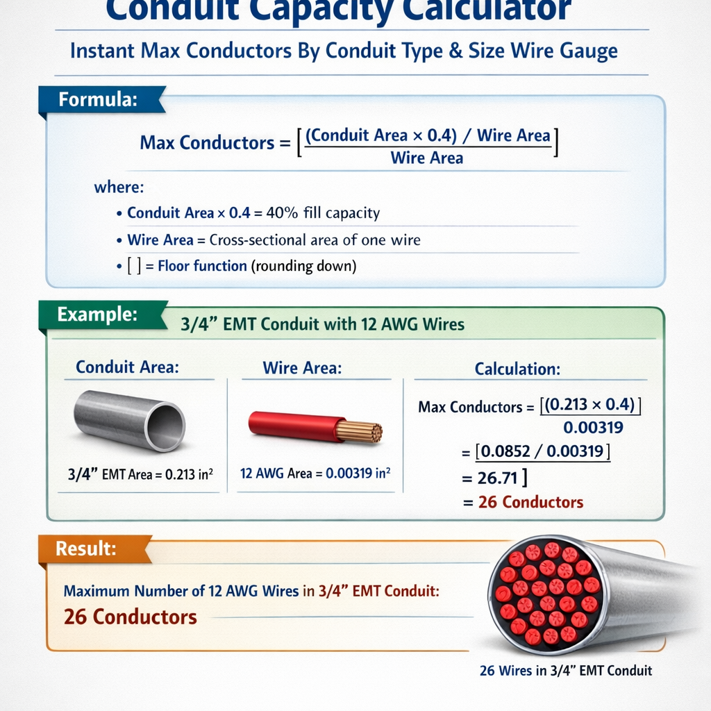
Worked example 1 — Max #12 THHN in 3/4" EMT (detailed step-by-step)
Problem statement: Determine the maximum number of insulated 12 AWG THHN conductors that can be installed in 3/4" EMT conduit, using typical values.
- Lookup conduit internal area: For 3/4" EMT, A_conduit = 0.533 in² (typical table value).
- Select fill factor: More than two conductors is expected, so F_fill = 0.40.
- Compute allowed fill area:A_allowed = A_conduit × F_fill = 0.533 × 0.40 = 0.2132 in²
- Obtain insulated conductor diameter for 12 AWG THHN (typical): d_ins = 0.130 in.
- Compute insulated conductor area:
A_cond = π × (0.130 / 2) × (0.130 / 2) = π × 0.065² = π × 0.004225 = 0.01327 in²
- Compute maximum number:N_max = floor( A_allowed / A_cond ) = floor( 0.2132 / 0.01327 ) = floor(16.07) = 16 conductors
- Interpretation: Using these typical values, 3/4" EMT can accommodate up to 16 × 12 AWG THHN insulated conductors under the "more than two" conductor fill rule. Note: If only two conductors were run, the fill factor would be 0.31 and acceptable counts would be lower (calculate separately).
Additional considerations:
- Verify that ampacity derating is applied if more than three current-carrying conductors are present. For example, 16 current-carrying conductors will require ampacity adjustment per NEC; this may force upsizing of the conductor gauge or conduit.
- Confirm manufacturer-insulated conductor diameter for the THHN product being used; actual diameters vary between brands.
Worked example 2 — Mixed scenario: three #8 THHN power conductors + one #10 THHN neutral + ground in 1" RMC
Problem statement: Evaluate fit and provide guidance for derating when installing three phase conductors (#8 THHN), one neutral (#10 THHN), and one equipment grounding conductor (#12 THHN) in 1" RMC. Assume conductor insulation diameters from the table and typical conduit area for RMC.
- Conduit internal area lookup: 1" RMC internal area (typical) = 1.049 in².
- Count conductors and determine the fill factor application: More than two conductors => F_fill = 0.40 and A_allowed = 1.049 × 0.40 = 0.4196 in².
- Determine insulated cross-sectional areas (typical):
- #8 THHN d_ins = 0.200 in → A_cond_8 = π × 0.100² = 0.0314 in² (per conductor)
- #10 THHN d_ins = 0.162 in → A_cond_10 = π × 0.081² ≈ 0.0206 in²
- #12 THHN d_ins = 0.130 in → A_cond_12 = 0.01327 in²
- Sum the required area:Total_required_area = 3 × A_cond_8 + 1 × A_cond_10 + 1 × A_cond_12Total_required_area = 3 × 0.0314 + 0.0206 + 0.01327 = 0.0942 + 0.0206 + 0.01327 = 0.12807 in²
- Compare to allowed area:A_allowed = 0.4196 in², Total_required_area = 0.12807 in² ⇒ Fits easily (0.12807 < 0.4196)
- Derating evaluation:
- Number of current-carrying conductors (per NEC rules) generally excludes the equipment grounding conductor. If the neutral carries only unbalanced currents in a multi-wire circuit and is a grounded neutral carrying only imbalance, it may not count as a current-carrying conductor for derating in certain situations; verify per NEC 310.15(B)(5) or applicable edition. Conservative approach: assume the neutral is current-carrying, giving 4 current-carrying conductors (three phase + neutral) which triggers derating if over three.
- Since there are 4 current-carrying conductors, ampacity must be adjusted using the NEC adjustment factor table (typical factor for 4 conductors ≈ 80%). The designer must ensure the selected #8 conductors, after derating, still meet required ampacity for the load.
- Engineering decision: Space in conduit is adequate, but ampacity derating may require conductor upsizing or splitting into additional conduits depending on continuous load and local code interpretation.
Handling mixed conductor sizes and cables
When mixing conductor sizes, the correct approach is to sum the actual insulated cross-sectional areas of each conductor and compare that sum to the allowed area A_allowed (not simply divide by a single conductor area). Multi-conductor cables occupy different geometry and are treated as equivalent cross-sectional areas or as cables with listed cross-sectional area per NEC; always use manufacturer cable area or NEC cable tables.
- Do not attempt to approximate mixed-size fills by averaging diameters; perform area summation for precision.
- When cables are present, NEC often requires counting the cable as one object with its listed area; cables can quickly consume conduit capacity.
Practical engineering warnings and AHJ considerations
- Always verify the edition of the NEC (or the local code) adopted by the AHJ. Table numbers and permissible percentages are consistent across many editions, but amendments and local exceptions exist.
- Manufacturer insulation diameters vary. Use the data sheet for the specific product when finalizing fill calculations.
- Temperature ratings, bundling, and insulation types (THHN vs XHHW-2) affect ampacity and must be coordinated with conduit fill decisions.
- Consider installation practicality: pulling tension, bends, and conduit fill affect pull force; often engineers limit fill below the maximum to ease installation and future maintenance.
- Equipment grounding conductors are counted differently for ampacity derating calculations; follow NEC guidance for counting current-carrying conductors.
Optimization techniques and instant calculator features
To provide a high-value "Instant Max Conductors By Conduit Type Size Wire Gauge" tool, implement these features:
- Database of conduit internal areas by type, trade size, and manufacturer tolerances, versioned per code edition.
- Database of insulated conductor diameters by manufacturer and insulation type (THHN, XHHW-2, etc.).
- Automated selection of F_fill based on number of conductors entered; support for mixed conductor lists and cables.
- Ampacity derating calculator that references NEC adjustment factors and provides recommended conductor upsizing if required.
- Pull tension estimator (optional) to flag impractical high-density fills for long pulls or multiple bends.
- Exportable calculation report including references to the normative tables, assumptions, and manufacturer datasheets for permitting and AHJ review.
Reference normative documents and authoritative links
- NFPA – National Fire Protection Association, NFPA 70, National Electrical Code (NEC). https://www.nfpa.org/NEC
- IEC – International Electrotechnical Commission (IEC 60364 series for electrical installations). https://www.iec.ch/
- IEEE – Institute of Electrical and Electronics Engineers (standards and guides for electrical design). https://www.ieee.org/
- NEMA – National Electrical Manufacturers Association (conduit and cable manufacturer standards, datasheets). https://www.nema.org/
- Local AHJ and national standards bodies (e.g., BSI in the UK, CENELEC in Europe) for jurisdictional requirements.
Summary of best practices for engineers
- Use NEC Chapter 9 tables and manufacturer datasheets for authoritative dimensions.
- Perform area-based summation for mixed conductor installs; do not rely on approximations.
- Flag ampacity derating consequences when current-carrying conductors exceed three and provide remedial choices.
- Prefer slightly lower than maximum fill for ease of pull and long-term maintainability.
- Document all assumptions and data sources in job submittals to the AHJ.
Appendix — Quick reference calculation examples (compact)
Quick formula recall:
- A_cond = π × (d_ins / 2)²
- A_allowed = A_conduit × F_fill
- N_max = floor( A_allowed / A_cond )
Example quick checks:
- 3/4" EMT and #12 THHN: A_conduit=0.533, F_fill=0.40, A_allowed=0.2132, A_cond≈0.01327, N_max≈16.
- 1" EMT and #10 THHN: A_conduit≈0.866, A_allowed≈0.3464, A_cond≈0.0206, N_max≈16.
End of technical reference. Always cross-check with the latest edition of the applicable electrical code and manufacturer datasheets before construction or permitting.