Arc flash mitigation requires precise calculations to evaluate incident energy and protective systems performance metrics.
Mitigation calculators reveal how faster clearing time and PPE selection reduce worker risk exposure levels.
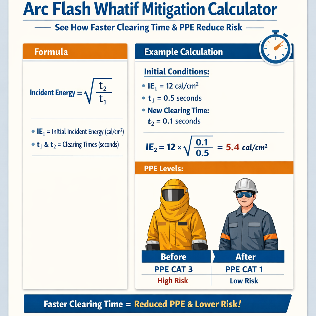
Arc Flash What‑If Mitigation Calculator — Compare Incident Energy vs Clearing Time and PPE
Arc flash risk framework and the role of "what-if" mitigation calculators
An arc flash what-if mitigation calculator is a decision-support tool that models how changes in system parameters (protective device clearing time, available fault current, working distance, system configuration, and PPE arc ratings) change calculated incident energy and therefore worker hazard. These calculators are used in engineering studies to evaluate mitigation strategies, quantify residual risk, and demonstrate compliance with standards such as IEEE 1584, NFPA 70E, IEC 61482 and OSHA regulations.Effective use of a calculator requires understanding both the underlying physics and the simplifying assumptions. Many calculators implement the IEEE 1584 empirical model or an equivalent relationship; others provide simplified proportional models for rapid sensitivity analysis. This article focuses on the technical basis of mitigation, the math linking clearing time and incident energy, the impact of PPE selection, practical examples, and normative references to support engineering decisions.Fundamental relationships: energy, current, distance and time
The incident energy (E) delivered to a worker during an arc flash event depends on the electrical power of the arc, duration of the arc, and geometric/radiative coupling between the arc and the worker. For rapid what-if comparisons and mitigation sizing, a common approximate proportionality is:E ≈ k × I2 × t / D2
Where:- E = incident energy at the worker (proportional to cal/cm2 or J/cm2).
- I = arcing current (A or kA). For relative comparisons use kA for convenience.
- t = arc duration (s) — primarily the protective device clearing time plus any intentional delay.
- D = working distance (same unit used consistently — inches or mm).
- k = proportionality constant which depends on unit system and radiative coupling; in many comparisons k cancels out when computing ratios.
Formalized IEEE 1584 relationship and practical interpretation
IEEE 1584 (2018) provides an empirically-derived model for predicted incident energy that depends on many parameters: system voltage, bolted short-circuit current, electrode configuration, enclosure size, grounded or ungrounded system, and working distance. Because the full expression is involved, practitioners frequently cross-check the detailed IEEE model against simplified proportional computations for rapid scenario ranking.Key takeaways consistent with IEEE 1584:- Incident energy increases with arcing current but not linearly; empirical exponents capture geometry and voltage effects.
- Incident energy scales roughly linearly with arc duration (shorter clearing times produce proportionally lower energy).
- Working distance is an inverse-squared effect for radiative intensity — doubling distance reduces incident energy by about 4× in first approximation.
Typical values and lookup tables
| Parameter | Typical Values / Common Options | Notes |
|---|---|---|
| Low-voltage system voltage | 208 V, 240 V, 480 V | Most industrial motor control centers and switchgear are 480 V. |
| Medium-voltage system voltage | 2.4 kV, 4.16 kV, 13.8 kV | Distribution transformers and medium-voltage switchgear. |
| Working distance (D) | 18 in (457 mm), 24 in (610 mm), 36 in (914 mm) | NFPA 70E commonly uses 18 in for many LV switchgear tasks. |
| Arcing current (I) | 1 kA to 50 kA | Arcing current may be a fraction of bolted fault current depending on arc impedance. |
| Protective device clearing time (t) | 0.02 s to 2.0 s | High-speed breakers or electronic relays clear in tens of milliseconds; thermal-magnetic breakers and fuses can take longer. |
| PPE arc rating classes | 4 cal/cm2, 8 cal/cm2, 25 cal/cm2, 40 cal/cm2 | Selected to exceed predicted incident energy with engineering margin. |
| Typical arc boundary distances | 12 in to 48 in | Calculated using incident energy or step-and-touch potential criteria. |
| Device type | Typical operating clearing time | Typical effect on incident energy |
|---|---|---|
| Fast electronic trip breaker | 0.01 s – 0.1 s | Can dramatically reduce E; up to 10x reduction compared to delayed devices. |
| Low-voltage fuse (current-limiting) | 0.01 s – 0.3 s | May limit peak current and reduce E via both I and t reduction. |
| Thermal-magnetic breaker (standard) | 0.1 s – 1.0 s (depends on fault magnitude) | Moderate reduction; slower clearing increases E. |
| Relay-protected feeder with intentional delay | 0.3 s – 2.0 s | Long delays multiply E; coordination may increase hazard. |
Formulas for mitigation analysis (HTML only)
Below are useful formulas presented in plain HTML for quick calculator design and sensitivity analysis. These are suitable for spreadsheet implementation and are intentionally unit-agnostic — keep units consistent throughout.Proportional incident energy model (relative):
E = k × I2 × t / D2
When comparing two scenarios with identical geometry and units, k cancels and the ratio is:
E2 / E1 = (I2 / I1)2 × (t2 / t1) × (D1 / D2)2
Required PPE arc rating selection (simple margin):
ARrequired = E × SF
Where:- E = calculated incident energy (cal/cm2).
- SF = safety factor, typical values range from 1.1 to 1.5 depending on company policy.
- ARrequired = minimum arc rating of clothing (cal/cm2).
Time to reduce incident energy to target (solve for t):
ttarget = tbase × (Etarget / Ebase) × (Ibase / Itarget)2 × (Dtarget / Dbase)2
Explanation:- These algebraic rearrangements let engineers compute how much faster a trip must be, or how much fault current must be reduced, to achieve a desireable incident energy quota.
- When only clearing time is varied (I and D constant), the relation reduces to ttarget = tbase × (Etarget / Ebase).
How faster clearing time reduces risk: theory and practice
Faster clearing time reduces incident energy almost linearly (for constant arc current) and can provide the most cost-effective mitigation in many systems. There are two separate benefits:- Reduction in cumulative thermal energy (incident energy) delivered to clothing and skin.
- Reduction in arc blast impulse and duration, which can reduce secondary injuries from blast pressure and shrapnel.
- Install fast electronic trip breakers with short instantaneous and short-time settings.
- Replace timed coordination with current-limiting devices where coordination is not essential.
- Use arc flash detection schemes that trip breakers faster than conventional overcurrent elements (e.g., optical sensors, differential protection).
- Employ zone-selective interlocking or adaptive protection to localize clearing to the nearest upstream device.
- Faster clearing may reduce selectivity — coordination study is necessary to ensure nuisance tripping does not disrupt process safety.
- Shorter clearing times may require upgrades in protection hardware and setting management.
- Cost-benefit analysis should consider reduced injury risk, potential insurance benefits, and worker safety priorities.
Quantifying PPE reduction effect
PPE does not reduce incident energy but reduces the severity of burns when incident energy is absorbed by clothing systems tested to specified arc ratings. If E = 8 cal/cm2 and PPE arc rating is 8 cal/cm2 with no margin, the exposure is at the threshold. Companies usually apply SF ≥ 1.1 to ensure reserve capacity:ARselected = 8 cal/cm2 × 1.25 = 10 cal/cm2
Therefore select an available PPE ensemble with arc rating ≥ 10 cal/cm2 — practically this means an 8 cal/cm2 garment may be insufficient; you would select 25 cal/cm2 class if required margins demand.Real-world examples with step-by-step solutions
Case 1 — Low-voltage motor control center (MCC) arc flash mitigation by clearing time improvement
Scenario data (measured / engineering estimate):- System voltage: 480 V, three-phase.
- Available bolted fault current at MCC bus: 30 kA.
- Estimated arcing current (Iarc): 8 kA (arcing current typically less than bolted).
- Working distance: 18 in (457 mm).
- Existing protective device: thermal-magnetic breaker, average clearing time at this fault level = 0.5 s.
- Company target: reduce incident energy to ≤ 8 cal/cm2 to avoid high-level PPE and facilitate safe work.
- Baseline calculated incident energy using detailed model: Ebase = 16 cal/cm2 (from IEEE 1584-compliant tool).
ttarget = tbase × (Etarget / Ebase)
Step 2 — Substitute known values:ttarget = 0.5 s × (8 / 16) = 0.5 s × 0.5 = 0.25 s
Interpretation: Clearing time must be reduced from 0.5 s to 0.25 s to halve incident energy to 8 cal/cm2. Options to achieve this:- Install a faster trip element or electronic breaker with instantaneous trip at the same pickup.
- Use current-limiting fuses whose clearing characteristics result in shorter t at high fault magnitudes and reduced Iarc.
- Implement arc flash detection sensors that command trip in <0.05 s; this would reduce E to <2 cal/cm2 if implemented successfully.
If t remains 0.5 s then E = 16 cal/cm2. Using SF = 1.25, ARrequired = 16 × 1.25 = 20 cal/cm2. Practical choice: 25 cal/cm2 PPE class.
Step 4 — Cost-benefit summary:- Breaker upgrade cost vs PPE recurring cost and exposure risk — typically faster clearing yields both safety and operational benefits.
- Coordination study required to maintain selectivity when faster trip settings are used.
Case 2 — Medium-voltage transformer secondary arc flash reduction using current limiting fuse
Scenario data:- System voltage: 4.16 kV transformer secondary feeding switchgear.
- Bolted fault at secondary: 20 kA.
- Arcing current estimate: 10 kA.
- Working distance: 24 in (610 mm).
- Existing protection: upstream relay with 0.6 s clearing time under coordination; baseline Ebase = 40 cal/cm2 (from detailed calculator).
- Mitigation option under study: apply current-limiting fuses at transformer primary or secondary to reduce both Iarc and t.
Enew / Ebase = (Inew / Ibase)2 × (tnew / tbase) × (Dbase / Dnew)2
Working distance unchanged so last ratio = 1.Step 2 — Substitute numerical values:Enew / 40 = (5 / 10)2 × (0.05 / 0.6)
Enew / 40 = (0.5)2 × 0.083333...
Enew / 40 = 0.25 × 0.083333... = 0.0208333...
Step 3 — Compute Enew:Enew = 40 × 0.0208333... = 0.8333 cal/cm2
Interpretation: A combination of current-limiting fuses that reduce arcing current by half and a dramatically faster clearing time (e.g., instantaneous fuse operation) can reduce incident energy by nearly 50× in this approximate proportional model and bring exposure into a range where minimal arc-rated PPE is required.Engineering caveats:- IEEE 1584 and IEC 61482 modeling must be used for final values; the proportional model demonstrates feasibility and order-of-magnitude improvements.
- Implementing fuses and faster clearing may have relay coordination, fault current interruption, and system stability impacts that must be assessed.
Practical workflow for using a what-if mitigation calculator
A recommended engineering workflow:- Gather accurate system data: voltages, transformer impedances, bolted fault currents at point of work, conductor spacing, enclosure geometry, and working distance.
- Run a baseline IEEE 1584-compliant calculation to obtain incident energy and arc boundary.
- List candidate mitigations: faster breaker, current-limiting fuse, arc flash detection, remote racking, zone selective interlocking, and increased working distance.
- Using the calculator, model each candidate parametric change individually and in combinations (what-if scenarios). Use the proportional relation for quick ranking and IEEE 1584 for confirmation.
- Document clearing-time targets, expected incident energy after mitigation, PPE class required, and any impacts on system coordination.
- Implement pilot changes (e.g., faster trip on a feeder), measure actual clearing times under controlled test conditions, and validate incident energy reduction with a follow-up study.
- Revise PPE policy and work procedures accordingly and maintain change control over protection settings.
Checklist for mitigation implementation
- Confirm protective device short-circuit interrupting rating and compatibility with existing equipment.
- Perform coordination study after changing instantaneous trip settings.
- Ensure maintenance and training on new PPE is documented and enforced.
- Keep recorded evidence of calculations and signed engineering judgments for compliance audits.
Normative references and external authority resources
Engineers should refer to authoritative sources when performing formal arc flash studies and implementing protection changes:- IEEE 1584-2018: IEEE Guide for Performing Arc-Flash Hazard Calculations. Provides the detailed empirical model used by most industry tools. Link: https://standards.ieee.org/standard/1584-2018.html
- NFPA 70E (latest edition): Standard for Electrical Safety in the Workplace. Provides PPE selection, work practices, and hazard/risk assessment guidance. Link: https://www.nfpa.org/codes-and-standards/all-codes-and-standards/list-of-codes-and-standards/detail?code=70E
- IEC 61482 series: Protective clothing against the thermal hazards of an electric arc. Relevant for PPE testing and selection. Link: https://webstore.iec.ch/publication/35784
- OSHA resources on electrical safety and PPE: https://www.osha.gov/electrical
- Manufacturer data sheets for breakers, fuses and relays — consult interrupting time-current curves and application notes for actual t(I) characteristics.
Limitations, uncertainties and recommended validation practices
When using what-if calculators and simplified proportional relationships, keep in mind:- Empirical models depend on electrode geometry and enclosure effects not captured by simple proportional formulas.
- Arcing current is not equal to bolted short-circuit current; measurement or conservative estimation is necessary.
- PPE performance varies with clothing layering, fit, and completeness of coverage; test data should be used for selection.
- Human factors: visibility, mobility, and reaction time during an arc event are not captured; engineering controls are preferred over relying solely on PPE.
- Use a certified IEEE 1584-compliant tool for final hazard numbers.
- Perform secondary verification after hardware changes by measuring actual fault-clearing times during planned tests and update calculations accordingly.
- Keep a record of protective device curves (time-current characteristic curves) and use them to compute expected clearing times at relevant multiple-of-pickup levels.
Operational considerations and best practices
Best practices for reducing arc flash risk using faster clearing time and PPE pairing:- Prioritize engineering controls that lower incident energy (faster clearing, current limiting, increased distance) ahead of administrative controls and PPE.
- Where PPE is required, define minimum arc rating requirements with a conservative safety factor and ensure PPE ensembles are compatible (head, face, torso, hands, feet).
- Use labeling on equipment with calculated incident energy, required PPE, working distance, and arc boundaries. Update labels after any protection setting changes.
- Implement a periodic review process: protection settings, system changes, and maintenance actions can change arc flash exposure and must trigger recalculation.
Summary of actionable engineering rules-of-thumb
- If you halve the clearing time (t → 0.5t) and leave current and distance constant, incident energy is approximately halved.
- Reducing arcing current by half reduces incident energy by roughly 4× if time and distance remain constant (since E ∝ I2).
- Doubling working distance reduces incident energy by about 4× (E ∝ 1/D2), making remote work and extended tools effective mitigations.
- Combining small improvements in multiple dimensions (I, t, D) often produces multiplicative reductions in incident energy making lower-cost mitigations viable.
- IEEE Std 1584-2018, IEEE Guide for Performing Arc-Flash Hazard Calculations.
- NFPA 70E, Standard for Electrical Safety in the Workplace (latest edition).
- IEC 61482, Protective clothing against the thermal hazards of an electric arc.
- OSHA: Electrical Standards (https://www.osha.gov/electrical).
- Equipment manufacturer technical literature and time-current characteristic (TCC) curves.
Final engineering recommendations
For any facility performing arc flash what-if mitigation studies:- Use a certified IEEE 1584-based calculator for final hazard ratings and labeling.
- Use simplified proportional relations to quickly screen candidates and determine whether faster clearing time or current-limiting devices will provide the desired reduction in incident energy.
- Quantify clearing-time targets and coordinate protection settings before hardware changes are finalized.
- Choose PPE with an appropriate safety factor and maintain rigorous PPE program management.
- Document all assumptions, data sources, and final settings to support compliance and future changes.