This cheat sheet maps US service voltage classes for electrical systems efficiently and accurately now.
Engineers, electricians, and technicians use this guide to quickly identify system voltages in design, maintenance.US Service Voltage Classes Calculator – Map Common Electrical Systems and Derived Voltages
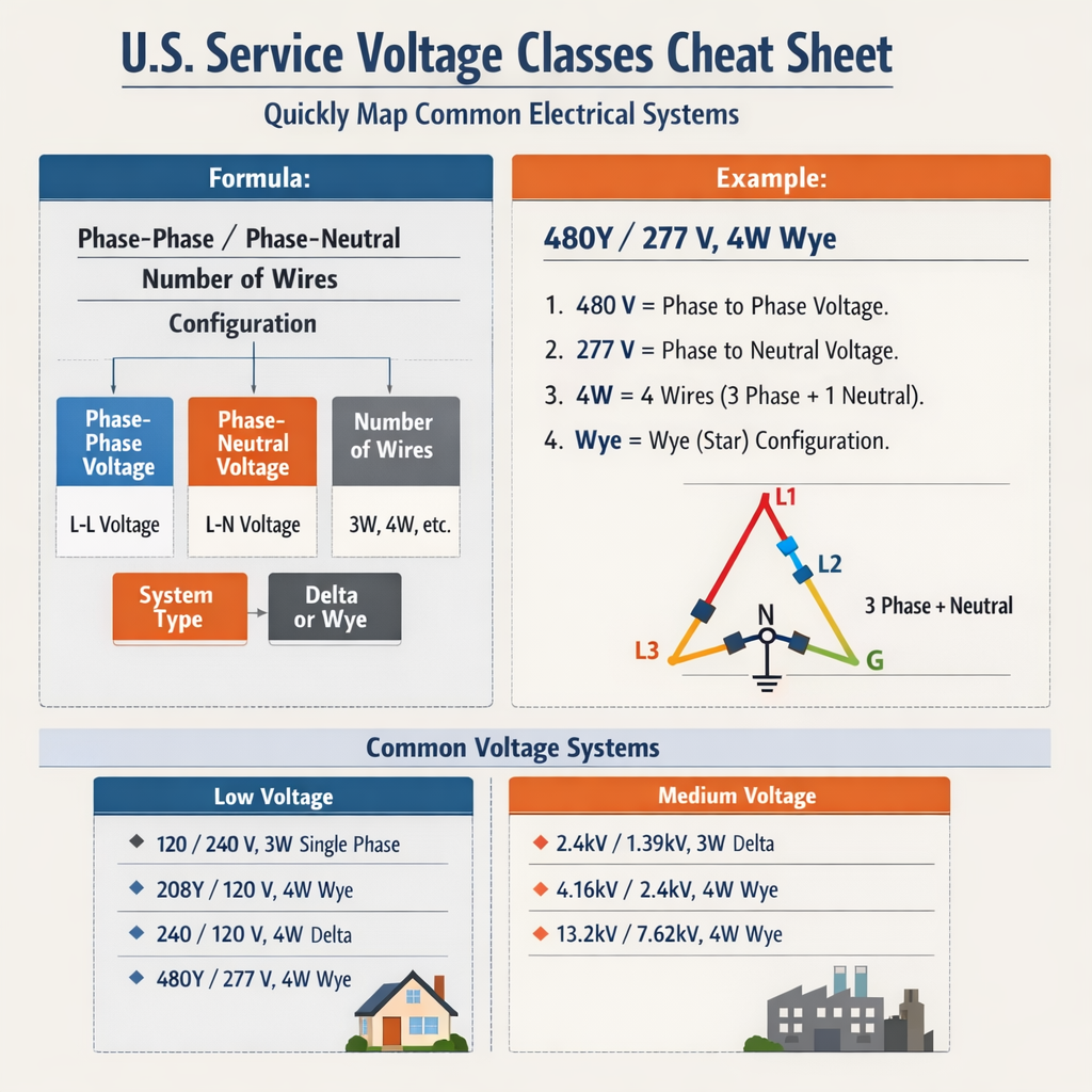
Scope, objectives, and practical use
This article provides a compact technical reference to map common US service voltage classes to real electrical system configurations. It is aimed at electrical engineers, electrical designers, field electricians, and facilities managers who need a rapid, authoritative mapping between nominal voltage classes, system types (Wye, Delta, high-leg), and typical application contexts.The guide emphasizes:- Nominal voltages commonly encountered in the United States and their phase-to-phase and phase-to-neutral relationships.
- How to compute currents and power for both single-phase and three-phase systems using simple formulas.
- Two fully developed worked examples with step-by-step calculations for transformer and service sizing.
- References to applicable standards and authoritative external sources for verification and compliance.
Overview of US service voltage classes
US electrical distribution uses a limited set of nominal voltage classes that repeat across residential, commercial, and industrial installations. The most common nominal classes include single-phase 120/240 V, three-phase 120/208 V (Wye), three-phase 277/480 V (Wye), and various delta configurations such as 240 V and 480 V delta. The nominal value indicates a design point; actual system voltages vary with loading and regulation and must comply with standards (e.g., IEEE Std C84.1, NFPA 70).Key system topology concepts:- Wye (Y) systems have a neutral conductor; line-to-neutral voltages are 1/√3 of line-to-line voltages.
- Delta (Δ) systems do not provide a neutral inherently, but center-taps or grounding arrangements may introduce a neutral.
- High-leg (wild-leg) delta systems provide both 240 V single-phase and 120 V center-tapped loads while retaining a high leg about 208 V to neutral.
Common US service voltages — quick reference tables
| System name | Configuration | Line-to-line (nominal) V | Line-to-neutral (nominal) V | Neutral present? | Typical applications | Notes / common sizes |
|---|---|---|---|---|---|---|
| 120/240 V split-phase | Single-phase center-tapped transformer | 240 | 120 | Yes (center tap) | Residential, small commercial | 120/240 V, service up to several hundred amps; common single-family loads |
| 120/208 V 3-phase Wye | 3Φ Wye | 208 | 120 | Yes | Low-voltage commercial buildings, lighting, receptacles | Common for lighting panels, office buildings |
| 277/480 V 3-phase Wye | 3Φ Wye | 480 | 277 | Yes | Commercial/industrial lighting, larger loads | Used when higher distribution voltages reduce current and conductor size |
| 240 V 3-phase Delta | 3Φ Delta | 240 | — (no neutral) | Optional (via center-tap) | Older industrial equipment, motors | Delta motors; center-tapped delta provides 120 V for control circuits |
| 480 V 3-phase Delta | 3Φ Delta | 480 | — (no neutral) | Optional | Large motors, industrial distribution | Often used with 480Y/277 transformers for branch circuits |
| High-leg (open) delta 120/240 V | 3Φ open-delta with center-tap | 240 | 120 on two phases; ~208 on high leg | Yes | Legacy commercial/industrial | High leg must be marked; neutral present from center-tap |
| 600 V class | 3Φ Wye/Delta | Up to 600 | Up to 347 (for 600Y/347) | Depends on configuration | Large industrial, distribution | NEC covers equipment rated up to 600 V as low-voltage distribution |
Notes on nominal vs actual voltages
Nominal voltages are target values; utility service voltage tolerance and transformer regulation affect the delivered voltage. IEEE Std C84.1 defines acceptable voltage ranges and utilization equipment voltage ratings. For design and equipment selection, always check nameplate ratings and applicable standard tolerances.Key electrical relationships and formulas
This section lists the essential formulas used to convert between voltages, compute currents, and determine power for single-phase and three-phase systems. Formulas are presented in plain HTML math notation, followed by variable explanations and typical values.Single-phase real power:
Equation: P = V × I × PF
- P = real power (watts, W)
- V = line-to-neutral or line voltage for single-phase (volts, V). Typical: 120 V, 240 V.
- I = current (amperes, A)
- PF = power factor (unitless, 0 to 1). Typical: 0.8–1.0 for resistive and motor loads.
Three-phase balanced real power (line-to-line voltage):
Equation: P = √3 × V_LL × I_L × PF
- P = total three-phase real power (W)
- √3 ≈ 1.732
- V_LL = line-to-line voltage (volts, V). Typical: 208 V, 480 V.
- I_L = line current (amperes, A)
- PF = power factor (0–1). Typical: 0.8–0.95 for many industrial loads.
Line-to-neutral and line-to-line relationship in Wye:
Equation: V_LN = V_LL / √3
- V_LN = phase voltage (line-to-neutral)
- V_LL = line-to-line voltage (phase-to-phase)
- Typical: For V_LL = 480 V, V_LN = 480 / 1.732 ≈ 277 V.
Current from power in three-phase:
Equation: I_L = P / (√3 × V_LL × PF)
- Compute I_L given P, V_LL, and PF
- Example typical PF = 0.9 for mixed loads
Single-phase current from power:
Equation: I = P / (V × PF)
- Useful for 120/240 V single-phase loads (split load or two-pole breakers)
Transformer and service sizing considerations
When mapping loads to service voltage classes, transformer primary/secondary rating, impedance, and inrush characteristics determine sizing. Key steps in sizing:- Inventory connected loads by type (lighting, receptacles, HVAC, motors) and power consumption (kW, kVA).
- Allocate continuous vs non-continuous loads per NEC: continuous loads require 125% sizing for conductors and overcurrent protection.
- Convert single-phase loads to equivalent three-phase kW or kVA when grouping onto a three-phase transformer.
- Apply diversity factors or demand factors per NEC/engineering judgment for buildings where loads are not simultaneous.
- Size conductors and protective devices using NEC ampacity tables and adjust for temperature, derating, and conduit fill.
Extensive current lookup table for common loads
This table gives the approximate full-load currents for common equipment at several service voltage classes. Use for quick mapping and preliminary sizing. Values are approximate and assume PF = 1 for resistive loads or nameplate kW converted to kVA.| Equipment / Load | kW | I at 120 V single-phase (A) | I at 240 V single-phase (A) | I at 208 V 3Φ (A) | I at 480 V 3Φ (A) | Notes |
|---|---|---|---|---|---|---|
| Small HVAC unit | 5 | 41.7 | 20.8 | 13.9 | 6.0 | Motor PF & efficiency reduce real current for same kW |
| Commercial kitchen range | 12 | 100.0 | 50.0 | 33.3 | 14.4 | Often split-phase or 3Φ depending on installation |
| Server rack (IT) | 3 | 25.0 | 12.5 | 8.0 | 3.6 | Typically distributed on 208Y/120 or 480Y/277 with PDUs |
| Industrial motor (20 HP) | 15 (approx) | — | — | 41.7 | 17.9 | 20 HP ≈ 15 kW; actual FLA from motor nameplate required |
| Lighting bank (LED) | 2 | 16.7 | 8.3 | 5.6 | 2.4 | LED loads are resistive-like; PF often >0.9 |
| Elevator drive | 10 | 83.3 | 41.7 | 27.8 | 12.0 | Variable frequency drives change current waveform and need harmonic considerations |
Detailed worked examples
Below are two real-world examples that demonstrate mapping loads to service voltage classes and performing the associated electrical calculations.Example 1 — Office building: sizing a 120/208 V three-phase service
Scenario: A three-story office building has the following connected loads:- Lighting: 18 kW (LED), continuous
- Receptacles and general-purpose: 25 kW, non-continuous
- Small HVAC rooftop units: 30 kW total (three units), non-continuous
- IT equipment: 9 kW, continuous
- Continuous loads: Lighting 18 kW + IT 9 kW = 27 kW. NEC requires sizing for continuous loads at 125% (1.25).
- Non-continuous loads: Receptacles 25 kW + HVAC 30 kW = 55 kW.
- Adjusted continuous = 27 kW × 1.25 = 33.75 kW.
- Total adjusted load = 33.75 kW + 55 kW = 88.75 kW.
- Apparent power S (kVA) = P / PF = 88.75 kW / 0.9 ≈ 98.61 kVA.
Equation: I_L = S × 1000 / (√3 × V_LL)
- S = 98.61 kVA; V_LL = 208 V
- I_L = 98.61 × 1000 / (1.732 × 208) ≈ 274.0 A
- Standard transformer sizes: 75 kVA, 100 kVA, 150 kVA are common. Calculated S ≈ 98.6 kVA → select 150 kVA only if load growth expected; otherwise a 100 kVA transformer is marginally adequate if growth limited.
- However 274 A suggests a service-main breaker rating: choose standard breaker 300 A (three-phase) and conductors sized accordingly per NEC ampacity tables (e.g., 3/0 Cu or 250 kcmil Al depending on temperature and derating).
- Assumed PF = 0.9; verify motor and IT PFs from nameplates.
- Applied NEC 125% for continuous loads; check local authority having jurisdiction (AHJ).
- Use a 100 kVA transformer if no foreseeable growth, but prefer a 150 kVA transformer for future expansion and to reduce voltage drop.
- Install a 300 A main breaker for 208Y/120 V service and size conductors per NEC Table 310.15(B)(16) with derating factors applied.
Example 2 — Industrial plant: mapping motor loads to 480 V service and transformer sizing
Scenario: An industrial plant requires a new 480 V three-phase supply for a motor bank consisting of:- Motor A: 50 HP (approx 37.3 kW)
- Motor B: 30 HP (approx 22.4 kW)
- Motor C: 25 HP (approx 18.6 kW)
- Motor A: 50 × 0.746 = 37.3 kW
- Motor B: 30 × 0.746 = 22.38 kW
- Motor C: 25 × 0.746 = 18.65 kW
- Total motor kW = 78.33 kW
- S = P / PF = 78.33 / 0.85 ≈ 92.15 kVA
Equation: I_L = S × 1000 / (√3 × V_LL)
- I_L = 92.15 × 1000 / (1.732 × 480) ≈ 110.9 A
- Across-the-line starting currents may be 5–7× the FLA depending on motor characteristics. For selective coordination and breaker sizing, consider locked-rotor currents and motor starter type (across-the-line, reduced-voltage).
- For service main sizing, continuous motor starting is not assumed, so the main may be sized lower; however the service must handle starting current transiently without nuisance trips using proper coordination.
- Calculated steady-state current ≈ 111 A. Choose a standard breaker rating of 125 A or 150 A depending on future expansion and fault considerations.
- Conductor sizing and breaker settings must account for motor inrush and NEC guidance for motor branch circuits and overcurrent protection (motor branch circuit OCPD typically sized per NEC 430).
- Specify motor branch circuit protection and starters per NEC Article 430 and manufacturer recommendations.
- Provide for harmonic mitigation and voltage dip checks if many motors start simultaneously.
Special cases and legacy systems
High-leg delta and open-delta utility services remain in older buildings. Key points:- High-leg delta (wild leg) supplies 120/240 V single-phase loads and a high leg approximately 208 V to neutral. The high leg must be identified at the panel and not used for single-phase 120 V loads.
- Open-delta configurations provide three-phase with only two transformers and are used for small loads when full three-phase capacity is not required. Transformer capacity and balancing require careful evaluation.
- Delta systems often power motors directly but lack a neutral; control circuits or lighting requiring neutral must be handled by separate transformers or center-taps.
Grounding, neutral, and safety considerations
Proper mapping of the neutral and grounding system is essential when translating service voltage classes into usable circuits:- Wye systems present a neutral suitable for single-phase loads; neutral must be sized for unbalanced currents and grounded at the service disconnect per NEC and grounding electrode conductor requirements (NEC Art. 250).
- Delta systems without neutral require grounding transformers or separate neutral provisions for 120 V circuits.
- Bonding and grounding must follow NFPA 70 (NEC), IEEE Std 142 (Green Book) for grounding practices, and OSHA regulations where applicable.
Practical mapping cheat sheet — quick identification rules
- If you see a three-phase panel labeled 208/120, it's a 120 V line-to-neutral system (208 V line-to-line) — typical for commercial.
- If lighting ballasts or signs list 277 V, the building likely has a 480Y/277 V system.
- Residential meters delivering 120/240 V center-tapped transformers provide two 120 V legs and a 240 V differential for large appliances.
- High-leg delta panels should have the wild leg marked orange per NEC requirements; do not connect 120 V single-phase loads to the wild leg.
Normative references and authoritative links
For design compliance and final verification consult the following standards and guidance documents:- NFPA 70 — National Electrical Code (NEC). https://www.nfpa.org/NEC (subscription/edition-specific rules apply)
- IEEE Std C84.1 — Voltage Ratings and Tolerances. https://standards.ieee.org/standard/C84_1-2016.html
- IEC 60038 — Standard voltages (for international comparison). https://www.iec.ch
- NEMA — National Electrical Manufacturers Association product standards and ratings. https://www.nema.org
- OSHA electrical safety guidance. https://www.osha.gov
- UL product safety listings (transformer and switchgear standards). https://www.ul.com
Practical checklist for field verification
Before equipment connection or alteration, verify:- Read utility service voltages and transformer nameplates; confirm line-to-line and line-to-neutral voltages with a calibrated meter.
- Identify system configuration (Wye, Delta, high-leg) and mark the wild leg if present.
- Confirm grounding electrode connections and main bonding jumper at service equipment.
- Check nameplate ratings for motors, transformers, and switchgear; do not exceed nameplate limits.
- Document assumed power factors and inertia loads for transient analyses and coordination studies.
Additional engineering considerations
- Harmonics: Nonlinear loads (VFDs, UPS, computers) produce harmonics. Service voltage class selection affects harmonic mitigation strategies; check IEEE Std 519 for harmonic limits and mitigation measures.
- Voltage drop: For long feeders, higher distribution voltages (e.g., 480 V) reduce current and voltage drop; compute voltage drop per conductor size and allow less than recommended percent drop (commonly 3% branch + 5% total).
- Coordination and protection: Breaker and fuse selection must consider short-circuit duty and selectivity; higher system voltages produce higher prospective fault currents.
- Phase balancing: Especially in 120/240 split-phase and delta systems, balance single-phase loads across phases to minimize neutral currents and heating.
Summary mapping table — one-page mental model
This compact mapping helps remember the common pairs:| Nominal label | Phase-to-phase | Phase-to-neutral | Topology | Where used |
|---|---|---|---|---|
| 120/240 V | 240 V | 120 V | Split-phase / center-tapped | Residential |
| 120/208 V | 208 V | 120 V | 3Φ Wye | Commercial low-voltage distribution |
| 277/480 V | 480 V | 277 V | 3Φ Wye | Commercial/industrial lighting and power distribution |
| 240 V Δ | 240 V | — | 3Φ Delta | Older industrial machines |
| High-leg 120/240 | 240 V | 120 V (two legs), ~208 V (high leg) | Open/high-leg delta | Legacy industrial/commercial |
- Produce downloadable tables in CSV format for quick reference.
- Perform a site-specific load calculation given equipment list and distances.
- Generate a one-page printed cheat sheet PDF optimized for field technicians.