This article explains a quick NEC load calculator for mobile home park site distribution design.
Procedures, formulas, tables, and code-compliant examples deliver rapid results for engineers and inspectors site owners.
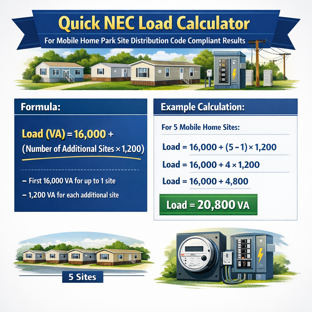
Quick NEC Load Calculator for Mobile Home Park Site Distribution (Diversified kVA and Feeder Current)
NEC-focused methodology overview for mobile home park site distribution
This section defines the systematic approach to compute feeder, transformer, and service capacities for mobile home parks using NEC principles and conservative engineering practice. The goal is to produce repeatable, auditable, and code-oriented load calculations that can be used to size distribution transformers, primary feeders, and secondary single-phase taps feeding individual lots.
Primary workflow (step-by-step)
- Inventory connected loads for each lot (lighting, small-appliance circuits, range, dryer, HVAC, water heater, receptacles).
- Express each load as VA (Volt-Amps) or kVA (kiloVolt-Amps). Convert nameplate watts to VA using PF where required.
- Apply NEC demand factors, or conservative engineering diversity factors where code tables do not directly apply.
- Sum demand-adjusted loads to obtain total site kVA required.
- Convert total kVA to three-phase primary current and select transformer standard size (kVA) with margin.
- Size feeders and overcurrent protection using NEC rules for continuous loads, conductor ampacity, and conductor temperature correction.
- Document load calculations and code references for permitting and inspection.
Key formulas (HTML-only math expressions) and variable definitions
All formulas are written using plain text HTML friendly syntax. Explanations of variables and typical values follow each formula.
- S = apparent power in volt-amps (VA). Typical units: VA or kVA (1 kVA = 1,000 VA).
- V = line-to-neutral voltage (V). Typical for residential service: 120 V or 240 V split-phase (120/240 V).
- I = current (A).
- S_kVA = apparent power in kVA. Typical per-lot values supplied in examples.
- V = 120 V or 240 V as appropriate.
- sqrt(3) = 1.7320508 (use 1.732 for hand calculations).
- V_LL = line-to-line voltage (V). Typical park primary distribution: 480 V or 600 V three-phase; secondary distribution transformers produce 240/120 single-phase.
- I = line current (A).
Convert single-phase totals to equivalent three-phase requirement (to size a central transformer): S_3ph_kVA = (Sum of single-phase kVA) / 1000
- If single-phase loads are evenly phase-balanced, divide total single-phase kVA among three phases. If not balanced, conservatively assume worst-phase loading when sizing neutral and overcurrent protection.
- P_connected_i = connected load for item i (VA or kVA).
- DF_i = demand factor for item i (unitless). Use NEC tables where applicable; otherwise use documented engineering diversity factors.
Feeder ampacity sizing for continuous loads: I_required = P_design_kW / (V_LL × PF) for three-phase, then apply NEC 125% if classified continuous (NEC 110.3(B), NEC 210.20, NEC 215.3).
Tables of common connected loads and typical demand factors
| Load Item | Typical Nameplate VA (per lot) | Typical DF (industry assumption) | Reference |
|---|---|---|---|
| General lighting (residential) | 3 VA/ft2 × 1,200 ft2 = 3,600 VA | 1.00 | NEC 220 guidance (use local code) |
| Small-appliance circuits (2 circuits) | 2 × 1,500 VA = 3,000 VA | 1.00 | NEC 220.52 |
| Electric range (typical) | 8,000 VA nameplate | Apply NEC 220.55 table (industry use 65% to 100% depending on quantity) | NEC 220.55 |
| Clothes dryer (electric) | 5,000 VA nameplate | Use nameplate unless aggregated and code table applies | NEC 220.54 |
| Electric water heater | 4,500 VA | 1.00 | Appliance nameplate |
| HVAC (split system) | 9,000 VA (typical 2.5 ton) | Consider HVAC diversity; use 100% for single unit per lot | Manufacturer and local amendments |
| Receptacles and small loads | 1,500 VA allowance (diversity assumed) | 0.60-1.00 based on park diversity | Engineering judgment |
| Park-level demand factors (industry practical guidance) | Notes |
|---|---|
| First mobile home: 100% of calculated connected load | Conservative; ensures adequate capacity for first loads. |
| Subsequent homes aggregated: 40% to 70% diversity | Typical applied DF range 0.40–0.70 depending on historic load diversity and climate. |
| Commercial laundry/treatment building: 100% until measured | Large constant loads should be treated individually and metered. |
| Common transformer kVA choices | Use case |
|---|---|
| 50 kVA | Very small parks or isolated clusters (≤ 4–6 lots depending on loads) |
| 150 kVA | Small parks (10–20 lots depending on per-lot connected load) |
| 300 kVA | Medium park (20–40 lots typical) |
| 500 kVA and above | Large parks (>40 lots or commercial loads) |
Sizing logic, continuous loads, and NEC compliance notes
- NEC requires that continuous loads be sized at 125% of the continuous current when selecting overcurrent protection and conductor ampacity. Treat HVAC or other loads that run longer than 3 hours as continuous.
- Use the appropriate NEC Article for the equipment: Article 220 for load calculations, Article 250 for grounding, Article 450 for transformer sizing, and Article 550 for mobile homes and parks.
- Always cross-check local amendments to the NEC and jurisdictional utility requirements for transformer installation, metering, and easements.
Real-world Example 1 — Small park (12 lots) detailed calculation
Assumptions per lot (typical manufactured home, documented assumptions):
- Living area: 1,200 ft2. General lighting: 3 VA/ft2 → 3,600 VA.
- Small-appliance circuits: 2 circuits × 1,500 VA = 3,000 VA.
- Electric range: nameplate 8,000 VA.
- Clothes dryer: nameplate 5,000 VA.
- Water heater: 4,500 VA.
- HVAC (2.5 ton): 9,000 VA.
- Miscellaneous receptacles and devices allowance: 1,000 VA.
Step 1 — Per-lot connected load (sum):
S_lot = 3,600 + 3,000 + 8,000 + 5,000 + 4,500 + 9,000 + 1,000 = 34,100 VA = 34.1 kVA
Step 2 — Park connected load (12 lots):
Step 3 — Apply conservative park diversity factor
Step 4 — Select transformer size and primary current (three-phase 480 V system chosen for distribution)
Compute three-phase primary current for 300 kVA at 480 V:
Step 5 — Feeder and overcurrent selection
Conservative design: treat major loads as continuous if HVAC or water heaters may run >3 hours. Apply 125% for continuous load protection.
Select 500 A overcurrent device and feeders sized for 500 A ampacity (e.g., copper or aluminum conductors sized per NEC Table 310.15 and local installation conditions).
Documented result: For 12 lots with assumed loads, a 300 kVA three-phase transformer with 500 A feeder is a code-consistent conservative design pending conductor temperature corrections and final local code checks.
Discussion and checks
- Balance secondary single-phase taps across phases to minimize neutral current and uneven loading.
- Secondary distribution taps: size single-phase taps (120/240 V) and local pedestals accordingly (e.g., 100 A per lot feeders if per lot service is 100 A).
- Implement individual lot overcurrent devices and distribution metering per local utility and NEC 230.
Real-world Example 2 — Medium park (30 lots) with mixed service sizes and phase balancing
Assumptions (mixed park):
- 20 lots with full-service homes (100 A typical). Per-lot connected load = 34.1 kVA (same as Example 1).
- 10 lots with smaller homes (50 A typical). For simplicity assume per-lot connected load = 18.0 kVA.
- One central laundry building with heavy load: 25 kVA nameplate.
Step 1 — Connected loads
Step 2 — Apply differentiated demand factors
- Full-size homes: DF_full = 0.65
- Small homes: DF_small = 0.50 (greater diversity)
- Laundry: DF_laundry = 1.0 (no diversity applied to central continuous load)
S_design = (682.0 × 0.65) + (180.0 × 0.50) + (25.0 × 1.0) = 443.3 + 90.0 + 25.0 = 558.3 kVA
Step 3 — Transformer and primary sizing
Choose next standard transformer size: 600 kVA three-phase
Primary current at 480 V:
Feeder sizing with continuous load allowance:
Select 1000 A rated feeder overcurrent protection and conductors sized to at least 1000 A ampacity (subject to conductor size tables and temperature correction factors).
Phase balancing and distribution taps
When distributing 30 single-phase loads across three phases, perform systematic balancing:
- List all single-phase loads and rank by expected demand hours.
- Allocate loads to Phase A, B, C to equalize expected kVA per phase.
- Control for asymmetric loads (laundry) by centering near a transformer secondary distribution or feeding from separate transformer winding where practical.
Example phase allocation (simplified): assume 20 full-size lots distributed 7, 7, 6 across A, B, C and small lots split 4, 3, 3 accordingly. Compute per-phase expected kVA and adjust.
Practical implementation considerations and checks
- Metering: Provide individual lot metering or master-meter arrangements per utility and local code. Verify NEC 230 and utility metering requirements.
- Overcurrent selection: Use NEC 240 to select upstream overcurrent protective devices and coordinate with distribution fuses and reclosers.
- Conductor temperature corrections: Adjust ampacity using NEC Table 310.15 and correction factors for ambient temperature, number of conductors in raceway, and soil thermal resistivity if direct-buried.
- Grounding and bonding: Follow NEC Article 250 and local utility grounding requirements. For multiple transformers, bond neutrals as required and provide grounding electrode systems for each separately derived system.
- Transformer inrush and harmonic considerations: For parks with many motors and A/C starting currents, consider transformer K-factor and inrush capacity. Specify impedance to limit voltage dip.
- Expansion allowance: Consider future expansion; select transformer and feeder sizes with spare capacity or plan for parallel transformers where required.
Checklist for submitting a code-compliant load calculation
- Detailed inventory of connected loads per lot with nameplate data and assumptions annotated.
- Applied demand factors (cite NEC table or state engineering basis) and calculations showing P_design.
- Transformer selection logic including kVA rounding rule and inrush/harmonic considerations.
- Feeder ampacity calculations showing continuous load adjustments (125% rule) and selected conductor sizes and insulation temperature ratings.
- Phase balancing plan and individual lot feeder plans and overcurrent protection.
- Grounding, bonding, and metering design notes with referenced NEC articles.
- Utility coordination and permit documentation references.
Normative references and authoritative resources
- NFPA 70, National Electrical Code (NEC) — primary reference for electrical load calculations and equipment sizing: https://www.nfpa.org/NEC
- NEC Article 220 — Branch-circuit, feeder, and service calculations: https://www.nfpa.org/NEC/NEC-codes
- NEC Article 550 — Mobile homes, manufactured homes, and mobile home parks: https://www.nfpa.org/NEC (search Article 550)
- NEC Article 450 — Transformers: https://www.nfpa.org/NEC
- IEEE and NEMA transformer application guides for inrush, harmonics, and K-factor considerations: https://standards.ieee.org and https://www.nema.org
- Manufactured Housing Institute — guidance on installation and park practice: https://www.manufacturedhousing.org
Final engineer remarks and best practices
Quick NEC load calculators for mobile home park distribution must balance speed with documented conservatism. Use conservative demand factors where code tables do not directly apply, but always reference NEC tables and local amendments when available. Maintain conservative transformer sizing (select the next standard KVA above calculated demand) and provide feeder ampacity with NEC continuous load multipliers applied. Always include phase balancing plans and account for central building loads separately.
When preparing design documents for permitting, include both the raw connected-load spreadsheet and the demand-adjusted result, with clear references to the NEC articles, tables, and any manufacturer nameplate data used. This approach produces code-compliant, auditable, and defensible results suitable for permitting, inspection, and field implementation.