This calculator streamlines receptacle branch circuit sizing for compliant electrical load calculations and design documentation.
Engineers instantly compute continuous load requirements, voltage drop, conductor selection with precise code-based methods.Receptacle Branch-Circuit Sizing Calculator (Required Ampacity and Continuous Load Capability)
Overview of receptacle branch circuit sizing methodology
Accurate receptacle branch circuit sizing requires a systematic workflow: quantify loads, classify continuous versus noncontinuous, apply code multipliers, select conductors and overcurrent protection, and verify voltage drop and derating constraints. This article presents formulas, variable definitions, typical values, tables with common conductor and breaker pairings, derating factors, and worked examples for immediate application.
Regulatory context and international considerations
Most jurisdictions adopt either the National Electrical Code (NEC, NFPA 70) or IEC/EN 60364 family rules; both require sizing for continuous loads and circuit protection. NEC Article references most commonly used in North America include:
- NFPA 70 (NEC) Article 210 (Branch Circuits)
- NEC 210.20(A) (Ampacity requirements)
- NEC 210.11 and 210.19 (branch-circuit requirements and conductor ampacity)
- NEC 220 (Load Calculations)
Internationally, IEC 60364 series and national amendments set similar requirements for continuous duty and conductor selection; designers must consult the applicable national code. Authoritative resources:
- NFPA – National Fire Protection Association: https://www.nfpa.org/NEC
- IEC – International Electrotechnical Commission: https://www.iec.ch
- IEEE Standards and technical guides: https://standards.ieee.org
- IAEI – International Association of Electrical Inspectors: https://iaei.org
Essential definitions and sizing rules
Continuous vs noncontinuous loads
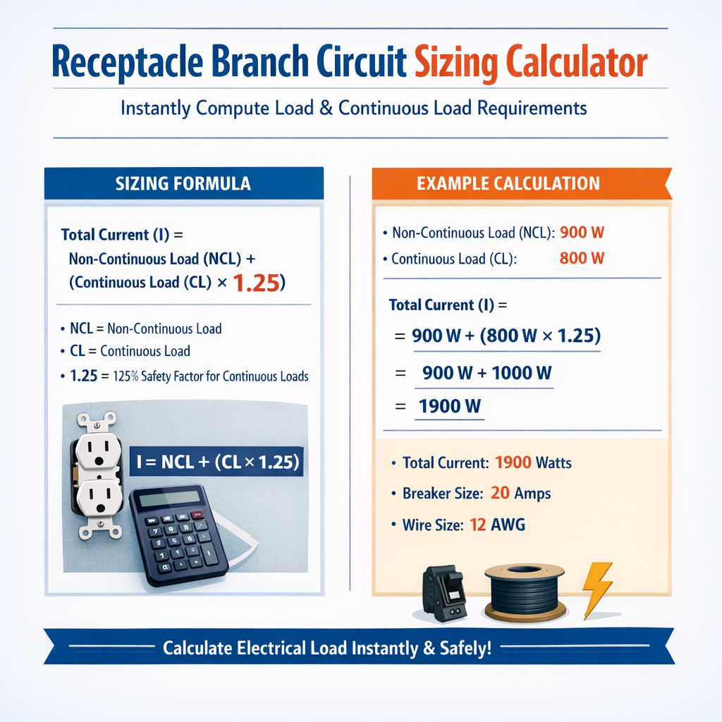
Continuous load: a load expected to run for three hours or more. Most codes require conductor ampacity and overcurrent protection to be sized at 125% of continuous load current.
General branch circuit sizing rule
For circuits supplying continuous and noncontinuous loads, use:
Where:
- I_required = minimum ampacity required for the circuit (A)
- I_continuous = total current of continuous loads (A)
- I_noncontinuous = total current of noncontinuous loads (A)
Power-to-current conversion (single-phase)
When loads are specified in watts or volt-amperes (VA), convert to current with:
Where:
- I = current (A)
- P = real power (W) or apparent power (VA) (W or VA)
- V = nominal system voltage (V)
- PF = power factor (unitless). Typical values: resistive loads PF ≈ 1.0, motors or electronics PF ≈ 0.8–0.95.
Voltage drop calculation
Design practice commonly limits voltage drop to 3% for branch circuits (2% for feeders when combined with branch circuits to maintain overall 5%). Use the round-trip conductor length method:
Variables explained:
- L = one-way conductor length from source to load (ft)
- I = load current (A)
- R_per_1000ft = conductor dc resistance (Ω per 1000 ft) at the applicable temperature
- V = system voltage (V)
Ambient temperature and conductor correction factors
Conductor ampacity must be corrected for ambient temperature and derated for more than three current-carrying conductors in a raceway. Typical corrections:
- Ambient correction factor (example values from NEC tables): for 75°C column, 30°C ambient factor = 1.00, 40°C factor ≈ 0.91, 50°C factor ≈ 0.82 — verify against applicable ampacity tables.
- Conductor count derating: more than three insulated current-carrying conductors in a conduit requires multiplying ampacity by a derating factor (e.g., 90% for 4–6 conductors, 70% for 10–20 conductors) — consult local code table.
Practical workflow for using a receptacle branch circuit sizing calculator
- Inventory loads connected to the circuit and categorize each as continuous or noncontinuous.
- Convert watts/VA to amperes using I = P ÷ (V × PF).
- Sum continuous currents and multiply by 1.25; add noncontinuous currents.
- Choose a circuit breaker rating at or above the required ampacity using standard sizing (15A, 20A, 30A, 40A, 50A, etc.).
- Select conductor gauge that provides required ampacity after ambient and grouping derating.
- Check voltage drop for the chosen conductor and run length; revise conductor if percent voltage drop exceeds design limit.
- Verify receptacle ratings, device temperature ratings (60°C/75°C/90°C), and overcurrent protection device trip curves for inrush/starting conditions.
| Breaker Rating (A) | Typical Min Copper Conductor (AWG) | Typical Maximum Continuous Load at 120 V (W) | Typical Application |
|---|---|---|---|
| 15 A | 14 AWG | 15 × 120 × 0.8 ≈ 1440 W (safe continuous ≈ 1440 W) | Lighting and general-purpose receptacles in small rooms |
| 20 A | 12 AWG | 20 × 120 × 0.8 ≈ 1920 W | Kitchen small-appliance branch circuits, outlets with appliances |
| 30 A | 10 AWG | 30 × 120 × 0.8 ≈ 2880 W | Small air-conditioning, dedicated appliance circuits |
| 40 A | 8 AWG | 40 × 120 × 0.8 ≈ 3840 W | Medium loads; water heaters or heavy tool benches |
| 50 A | 6 AWG | 50 × 120 × 0.8 ≈ 4800 W | Ranges, clothes dryers (depending on configuration), large appliances |
| AWG | Approx. DC Resistance (Ω / 1000 ft) | Typical Ampacity (NEC conservative guidance) |
|---|---|---|
| 14 | 2.525 Ω/1000 ft | 15 A (branch circuit typical) |
| 12 | 1.588 Ω/1000 ft | 20 A |
| 10 | 0.999 Ω/1000 ft | 30 A |
| 8 | 0.6282 Ω/1000 ft | 40 A |
| 6 | 0.3951 Ω/1000 ft | 50 A |
| 4 | 0.2485 Ω/1000 ft | 70 A |
Formulas and worked symbolic examples
Below are core formulas used by an instant receptacle branch circuit sizing calculator. Each formula is followed by variable explanations and typical values.
1) Convert load to current
- P = power (W or VA). Typical values: laptop 65–150 W, space heater 1500 W, desktop computer 300–600 W.
- V = nominal voltage. Typical single-phase service: 120 V (North America), 230 V (most international installations).
- PF = power factor. Typical for resistive loads = 1.0; for electronic loads use 0.9–0.95 unless measured.
2) Continuous load ampacity requirement
- I_continuous = sum of currents from loads expected 3 hours or more.
- I_noncontinuous = sum of currents from intermittent loads.
3) Voltage drop (single-phase, round-trip)
- Design guideline: V_drop ≤ 3% for branch circuits; total feeder + branch ≤ 5%.
Example 1 — Single continuous space heater on a dedicated receptacle
Scenario:
- One 1500 W space heater plugged into a dedicated 120 V receptacle.
- Cable run: 50 ft one-way from panel to receptacle.
- Ambient temperature 30°C, few conductors in conduit (no grouping derating).
Step 1: Convert power to current:
Step 2: Apply continuous load multiplier (125%):
Step 3: Choose standard breaker rating and conductor:
- Standard breaker sizes: 15 A or 20 A. 15 A breaker rating would be less than I_required (15.625 A) and is therefore not acceptable for a continuous 1500 W load by code.
- Therefore select a 20 A breaker and at least 12 AWG copper conductor.
Step 4: Voltage drop check. Use R_per_1000ft for 12 AWG = 1.588 Ω/1000 ft.
V_drop = I_design × R × length/1000. Use design current for V_drop — use actual load current or I_required; conservative approach uses I_required (15.625 A):
Result: Voltage drop 2.07% < 3% guideline — acceptable. Final selection: 20 A breaker, 12 AWG copper THHN/insulation rated at appropriate temperature column.
Example 2 — Small office with multiple continuous computing loads
Scenario:
- 12 office workstations, each with laptop docking station and monitor. Estimate 325 W continuous per workstation (server/PC, monitor, peripherals).
- Circuits are 120 V single-phase. Loads are expected to be continuous during business hours (>3 hours).
- One cable run 70 ft one-way from panel to branch circuit distribution.
Step 1: Total continuous power:
Step 2: Convert to current:
Step 3: Apply continuous multiplier:
Step 4: Choose breaker and conductor. Standard single breakers: 40 A insufficient (less than 42.76 A). Next standard: 50 A.
50 A breaker with 6 AWG copper conductor is typical; verify conductor ampacity and device rating for continuous duty (temperature column). Alternatively, split into two 20 A circuits: technical and code considerations must be checked for multi-receptacle loading and balancing.
Design choice A — Single 50 A circuit:
- Conductor: 6 AWG copper (typical ampacity 55–65 A depending on terminations and temperature rating) — verify ampacity after ambient correction.
- Voltage drop check using R_per_1000ft for 6 AWG = 0.3951 Ω/1000 ft. Round-trip length = 140 ft.
Design choice B — Split into two 20 A circuits (recommended for occupancy and distribution):
- Divide loads into two groups of six workstations: each group power = 6 × 325 = 1950 W
- I_group = 1950 ÷ (120 × 0.95) = 17.11 A
- I_required_group = 1.25 × 17.11 = 21.39 A → requires 30 A device or better to be conservative. However typical approach is to use two 20 A circuits if duty permits; because 21.39 A > 20 A, two 20 A circuits would be undersized per continuous load rules. Therefore split into three 20 A circuits (4 workstations per circuit): each circuit load = 4 × 325 = 1300 W → I = 1300 ÷ (120 × 0.95) = 11.39 A → I_required = 14.24 A → fits 15 A breaker? No, 15 A not adequate for 14.24 A continuous (since 15 A > 14.24? Actually continuous 125% * 11.39 = 14.24 A < 15 A, so 15A breaker may be acceptable by ampacity but 15A conductors are AWG14 — some designers prefer 20A circuits for computer clusters). Best practice: use three 20 A circuits (12 AWG) to provide margin and plugin diversity.
Conclusion: Either single 50 A feeder with sub-distribution, or three 20 A branch circuits, are practical solutions depending on distribution strategy. Document the selected option and confirm with local code authority.
Other practical considerations for receptacle branch circuit sizing
- Device ratings: ensure receptacle and connector ratings match circuit ampacity and environmental conditions.
- Harmonic loads: electronic equipment with switching supplies may increase neutral currents due to triplen harmonics; evaluate neutral sizing and consider 4-wire runs and derating accordingly.
- Inrush currents: motors and some electronics have high starting currents; select protective devices with appropriate trip characteristics or use soft-start methods when necessary.
- Multiwire branch circuits: ensure simultaneous disconnect and handle-tied breakers as required by code (NEC 210.4).
- Diversified loading: some load types allow demand factors per code (NEC 220 demand factors); apply only if code permits.
Expanded tables: voltage drop examples for common conductor sizes
| AWG | R (Ω / 1000 ft) | One-way length (ft) | Round-trip length (ft) | V_drop at 20 A (V) | Percent V_drop |
|---|---|---|---|---|---|
| 12 AWG | 1.588 | 50 | 100 | 3.18 | 2.65% |
| 12 AWG | 1.588 | 100 | 200 | 6.36 | 5.30% |
| 10 AWG | 0.999 | 100 | 200 | 3.998 | 3.33% |
| 8 AWG | 0.6282 | 150 | 300 | 3.77 | 3.14% |
| 6 AWG | 0.3951 | 200 | 400 | 3.16 | 2.63% |
Checklist for instant calculator implementation and verification
- Input: list each receptacle with rated or estimated wattage and whether continuous.
- Input system voltage and assumed power factor for electronic loads.
- Calculate I for each load using I = P ÷ (V × PF).
- Aggregate continuous loads, apply 125% multiplier, and add noncontinuous currents.
- Select nearest higher standard breaker and conductor size that meets ampacity after derating.
- Compute voltage drop using conductor resistance table; maintain ≤3% for branch circuits.
- Confirm terminations allow the chosen temperature column rating for conductor ampacity.
- Document code citations and assumptions for permit review.
References and further reading
- NFPA 70, National Electrical Code (NEC). Official site: https://www.nfpa.org/NEC
- IEC 60364 series: Electrical Installations of Buildings — consult national adoptions (CENELEC, BSI, etc.). IEC summary: https://www.iec.ch
- IEEE Std 141 (Green Book) and IEEE Std 142 for grounding and load considerations: https://standards.ieee.org
- NEMA and manufacturer technical data for conductor resistance and ampacity tables: https://www.nema.org
- IAEI technical articles for branch circuit design and inspector guidance: https://iaei.org
Final notes and professional practice
Use the presented formulas and tables as deterministic starting points for rapid sizing. Always verify selections against the controlling code text, equipment manufacturer data, and local authority having jurisdiction (AHJ). When in doubt, increase margin: choose the next larger conductor or breaker rating consistent with code to provide operational headroom. For installations involving harmonics, large motors, or unusual duty cycles, perform a specialized analysis or consult a professional electrical engineer.
SEO and documentation tips for deliverables
- Include the calculation inputs, intermediate steps, and final selections in the design package for traceability.
- Annotate the used code clauses (NEC or national equivalents) and any demand factors or exceptions applied.
- Provide a simple table summary per circuit: loads, continuous/noncontinuous, I_required, breaker, conductor, voltage drop %, and comments.