This technical article explains temperature correction calculations for conductors in AWG and mm2 standards globally.
It provides formulas, normative references, tables, worked examples, and practical guidance for engineers design calculations.
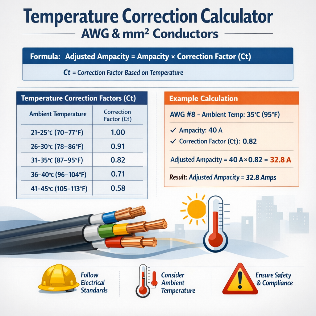
Temperature Correction Calculator for Conductor Ampacity (AWG and mm², standard-based)
Scope, normative context and application
This document explains how to calculate temperature correction for conductor ampacity using AWG and metric (mm2) cross-sections, aligned with widely used international normative sources (NEC/NFPA, IEC, BS/EN). The procedures and examples show practical calculation steps, formulas in plain HTML, and references to official tables. Always confirm final values with the applicable national code or the project’s specified edition of the normative document.
Fundamental principle and basic working formula
Electrical current rating (ampacity) of a conductor is limited by allowable conductor temperature and the conductor’s ability to dissipate heat to ambient. Temperature correction adjusts a reference ampacity (I_base) for ambient temperature or elevated operating conditions.
Primary correction formula
Use the following primary algebraic relation:
- I_corr: corrected continuous current rating (A).
- I_base: reference ampacity (A) taken from a standard table for a given insulation temperature rating and installation condition (single conductor, 30°C ambient, etc.).
- C_t: temperature correction factor (dimensionless) for ambient temperature and insulation rating—obtain from normative table or by interpolation.
- C_g: grouping or adjustment factor for multiple current-carrying conductors or other installation conditions (dimensionless).
Notes: I_base depends on the table chosen (NEC/IEC/BS). C_t and C_g must be taken from the same normative basis as I_base or applied according to that code’s rules.
How to obtain I_base and correction factors
- Identify the conductor material (copper or aluminium), construction (stranded/solid), and insulation temperature rating (e.g., 60 °C, 75 °C, 90 °C).
- Select the normative table for the installation condition: single conductor in free air, buried, conduit with more than three conductors, trays, etc.
- Read I_base from that table (this is typically for a reference ambient temperature — often 30 °C in many standards).
- Obtain C_t for the actual ambient temperature and insulation rating from the corresponding correction-factor table.
- Apply any grouping or bundling factor C_g from the standard.
Interpolation formula for correction factors
If the normative correction table gives discrete ambient temperature points and your actual ambient temperature lies between two table values, perform linear interpolation:
- C_t: interpolated correction factor.
- T_a: actual ambient temperature (°C).
- T_low, T_high: the lower and upper ambient temperatures from the normative table bracketing T_a (°C).
- C_low, C_high: correction factors corresponding to T_low and T_high (dimensionless).
Resistance temperature dependence (theoretical relation)
When needed for thermal modelling or approximate verification, conductor dc resistance changes with temperature as:
- R_T: conductor resistance at temperature T (Ω).
- R_ref: reference resistance at reference temperature T_ref (commonly 20 °C or 25 °C).
- α: temperature coefficient of resistivity. For copper α ≈ 0.00393 per °C at 20 °C; for aluminium α ≈ 0.00403 per °C.
- T: conductor temperature (°C).
- T_ref: reference temperature (°C).
Because conductor heating P = I^2 × R, the steady-state current capability will reduce as R increases; however, practical codes provide tabulated correction factors C_t to account for thermal environment and insulation limits instead of requiring direct thermal simulation for routine sizing.
Typical AWG table: cross-section, diameter and reference ampacity (illustrative)
| AWG | Area (mm2) | Diameter (mm) | Typical reference ampacity (A)* |
|---|---|---|---|
| 14 | 2.08 | 1.63 | 20 |
| 12 | 3.31 | 2.05 | 25 |
| 10 | 5.26 | 2.59 | 35 |
| 8 | 8.37 | 3.26 | 50 |
| 6 | 13.3 | 4.12 | 65 |
| 4 | 21.2 | 5.19 | 85 |
| 2 | 33.6 | 6.54 | 115 |
| 1 | 42.4 | 7.35 | 130 |
| 1/0 | 53.5 | 8.25 | 150 |
| 2/0 | 67.4 | 9.27 | 175 |
| 3/0 | 85.0 | 10.40 | 200 |
| 4/0 | 107.2 | 11.68 | 230 |
*Typical reference ampacity shown as guidance (commonly found for copper conductors, single conductor free-air conditions, 75 °C insulation column). Verify with the code edition you are using.
Typical metric (mm2) conductor table: cross-section and reference ampacity (illustrative)
| Cross-section (mm2) | Nominal diameter (mm)† | Typical reference ampacity (A)* |
|---|---|---|
| 1.5 | 1.38 | 16 |
| 2.5 | 1.78 | 24 |
| 4 | 2.26 | 32 |
| 6 | 2.76 | 40 |
| 10 | 3.57 | 55 |
| 16 | 4.51 | 70 |
| 25 | 5.64 | 95 |
| 35 | 6.69 | 125 |
| 50 | 8.05 | 150 |
| 70 | 9.46 | 200 |
| 95 | 11.0 | 250 |
†Nominal diameters are approximate for single solid round conductors. *Ampacity values are approximate reference figures and vary with standard, installation method and insulation temperature rating.
Temperature correction factor examples and table (illustrative)
Different codes publish correction-factor tables that map ambient temperature to a multiplicative factor for each insulation temperature rating. The following table gives a set of illustrative factors to demonstrate methodology; always use the table from the code in force for your project.
| Ambient (°C) | C_t for 60 °C insulation | C_t for 75 °C insulation | C_t for 90 °C insulation |
|---|---|---|---|
| 25 | 1.05 | 1.03 | 1.00 |
| 30 | 1.00 | 1.00 | 1.00 |
| 35 | 0.94 | 0.97 | 0.98 |
| 40 | 0.88 | 0.91 | 0.94 |
| 45 | 0.82 | 0.85 | 0.90 |
| 50 | 0.75 | 0.78 | 0.86 |
| 60 | 0.64 | 0.67 | 0.76 |
| 70 | 0.52 | 0.58 | 0.65 |
These numbers are illustrative; typical published tables (e.g., NEC, IEC) must be used to obtain exact C_t values per insulation class.
Grouping and other adjustment factors
Grouping/bundling factors (C_g) depend on how many current-carrying conductors share ducts, conduits, or trays. Typical rules (summarized):
- 1–3 current-carrying conductors: C_g = 1.0 (no derating in many codes).
- More than 3 conductors: progressive derating steps depending on count (e.g., 4–6, 7–9, 10–20 etc.).
- Large bundles or back-to-back installations require thermal analysis and specific code factors.
Always extract C_g from the normative table in the code applied to the project (NEC/IEC/BS). For example, a common grouping factor sequence (illustrative) may be 0.8 for 10–20 conductors and lower for larger bundles.
Worked example 1 — AWG conductor in conduit (step-by-step)
Problem statement: Determine corrected continuous ampacity for a copper AWG 6 conductor, used as a single phase conductor inside conduit, with the following conditions:
- I_base: use typical reference ampacity for AWG 6 (from the AWG table above): 65 A (copper, 75 °C insulation, single conductor reference).
- Ambient temperature: 40 °C.
- Insulation rating: 75 °C.
- Number of current-carrying conductors in the conduit: 4 (phase conductors only for derating calculation; neutral counted if it carries current).
Step 1 — Identify I_base
I_base = 65 A (from the AWG reference table; this is the typical 75 °C column value).
Step 2 — Obtain temperature correction factor C_t
From the illustrative C_t table above, for T_a = 40 °C and 75 °C insulation, C_t = 0.91.
Step 3 — Obtain grouping factor C_g
Assume code requires derating for more than three current-carrying conductors. For this example, use an illustrative grouping factor C_g = 0.8 for 4 conductors (verify with your code—this is an example).
Step 4 — Compute corrected ampacity
Result and interpretation
The corrected continuous ampacity is 47.3 A. Round and select protective device and conductor size according to the code’s sizing rules, conductor protection and permissible overcurrent device ratings. If the load continuous current is higher than 47.3 A, upsize the conductor or reduce conductor count per conduit or use higher temperature-rated insulation if permitted.
Worked example 2 — Metric conductor in tray with elevated ambient
Problem statement: A three-phase motor feeder uses three current-carrying copper conductors of 10 mm2 in a ventilated tray. Conditions:
- I_base: use 10 mm2 typical reference ampacity from metric table above: 55 A (single conductor reference).
- Ambient temperature: 50 °C.
- Insulation rating: 90 °C.
- Current-carrying conductors: 3 (three-phase conductors only; neutral not counted if balanced per code).
Step 1 — I_base
I_base = 55 A (typical reference for 10 mm2).
Step 2 — C_t from illustrative table
For T_a = 50 °C and 90 °C insulation, C_t = 0.86 (illustrative table above).
Step 3 — C_g (grouping)
With three current-carrying conductors, many codes permit no derating: C_g = 1.0 (confirm with the applicable code; here we assume C_g = 1.0).
Step 4 — Compute corrected ampacity
Result and interpretation
The corrected ampacity is 47.3 A. If the motor full-load current exceeds this value, you must upsize the conductors or choose a higher rated installation method, change tray arrangement, or use conductors with higher permissible temperature rating according to the code.
Detailed verification and practical notes
- Always use the correction-factor table published in the code edition adopted for the project (NEC, IEC 60364, BS 7671, etc.). Use interpolation for temperatures between table points.
- Confirm how the code counts current-carrying conductors: neutrals often excluded if balanced in certain systems, but included in others—read the rule text carefully.
- Continuous loads often require conductor sizing at 125% of continuous current (check your code: e.g., NEC requires 125% for continuous loads). Apply derating factors before comparing to the conductor’s corrected ampacity.
- For aluminium conductors apply material-specific I_base and α values when modelling resistance changes.
- For long runs, voltage drop must be checked separately; increased conductor size might be necessary despite adequate corrected ampacity.
Algorithm summary for a temperature correction calculator
- Input: conductor size (AWG or mm2), material, insulation rating, installation method, number of current-carrying conductors, ambient temperature, continuous vs. non-continuous.
- Lookup I_base from normative tables for the chosen installation method and insulation rating.
- Lookup C_t for the ambient temperature and insulation rating. If needed, interpolate.
- Lookup C_g for number of current-carrying conductors and installation method.
- Compute I_corr = I_base × C_t × C_g.
- Apply continuous-load multiplier if required by code (for continuous loads, multiply operating current by 125% and ensure it is ≤ I_corr, or adjust conductor size accordingly).
- Verify voltage drop and short-circuit and mechanical requirements.
Normative references and authoritative resources
- NFPA 70 — National Electrical Code (NEC). Official site: https://www.nfpa.org/ (consult the adopted edition for your jurisdiction).
- IEC 60364 series — Electrical installations of buildings. IEC Webstore: https://www.iec.ch/ (refer to Part 5-52 for selection and erection of electrical equipment).
- IEC 60502 — Power cables with extruded insulation. IEC webstore for product standards.
- BS 7671 — Requirements for Electrical Installations (IET Wiring Regulations), available via BSI/IET: https://www.theiet.org/.
- IEEE Std. and CENELEC documents for transmission/distribution; consult IEEE Xplore and CENELEC for region-specific guidance.
- Manufacturer technical guides and product datasheets (e.g., cable manufacturers and system suppliers) for practical installation correction guidance and thermal characteristics.
These references contain the official tabulations and detailed rules for counting current-carrying conductors, continuous load multiplication, and installation categories—use them for design and verification.
Best practices and verification checklist
- Confirm the edition and jurisdictional adoption of the normative standard before starting calculations.
- Use the exact table numbers and columns for the installation category chosen (e.g., conduit, free air, buried).
- Document I_base source, C_t and C_g values with table references and edition year in the project calculations.
- Round corrected ampacity per code rounding rules and select next standard conductor size if required.
- Perform voltage-drop checks and short-circuit checks separately from ampacity checks.
- When in doubt, perform a thermal simulation for clustered cables or critical installations and consult the manufacturer.
Final engineering reminders
- Temperature correction calculations protect insulation and lifespan: a conservative approach reduces failure risk.
- Codes evolve — periodically review standards updates (NEC cycles, IEC amendments) as correction factors and guidance may change.
- Always reconcile the calculated I_corr with practical protection device standard ratings and installation constraints; use professional judgment and peer review for critical designs.
- NFPA: https://www.nfpa.org/ (NEC / NFPA 70)
- IEC 60364 information: https://www.iec.ch/
- British Standards Institution / IET: https://www.theiet.org/ (BS 7671)
- ISO/IEC and regional standards libraries for conductor and cable product standards (e.g., IEC 60502).
- General AWG and metric conductor conversion references (engineering handbooks and manufacturer tables).
Implement the formula I_corr = I_base × C_t × C_g in your calculator using authoritative tabular inputs and the interpolation method shown. Always annotate results with the normative source used and the edition date.