This guide addresses unit substation grounding and service versus SDS NEC requirements precisely for planners.
It explains verification, calculations, bonding, grounding electrode systems, fault currents, and configuration steps for compliance.
Unit Substation Grounding: NEC Table vs SDS (Adiabatic) — Quick sizing and comparison
Scope and applicability for unit substation grounding and SDS NEC compliance
This document describes grounding design and verification methods for unit substations, service equipment, and Service Disconnect Switches (SDS). It compares grounding requirements under NFPA 70 (NEC) with IEEE substation grounding practice and provides practical, stepwise configuration procedures for compliance, safety, and performance.It targets:- Electrical engineers performing grounding design for pad-mounted or indoor unit substations.
- Commissioning teams verifying NEC 250 compliance at service equipment and SDS installations.
- Maintenance and safety personnel responsible for step-and-touch potential mitigation and bond integrity.
Key terms and definitions
Unit substation
A factory-assembled transformer and switchgear assembly that provides service to a facility through a packaged unit with integrated grounding components.SDS (Service Disconnect Switch)
SDS refers to the main service disconnect or fused switch where the utility or building service terminates and where bonding to grounding electrodes is required by NEC.Grounding electrode system and grounding electrode conductor (GEC)
The assembly of electrodes (rods, plates, concrete-encased electrodes, water piping, etc.) connected to the electrical system to establish an earth reference. The conductor that bonds the system neutral or service equipment to this electrode system is the GEC.Regulatory and normative references
- NFPA 70, National Electrical Code (NEC), Article 250 — Grounding and Bonding: https://www.nfpa.org/NEC
- IEEE Std 80 — Guide for Safety in AC Substation Grounding: https://standards.ieee.org/standard/80-2013.html
- IEEE Std 142 — Recommended Practice for Grounding of Industrial and Commercial Power Systems: https://standards.ieee.org/standard/142-2007.html
- OSHA Electrical Safety: https://www.osha.gov/electrical
- IEC 61936-1 — Power installations exceeding 1 kV AC: https://www.iso.org/standard/29538.html
NEC 250 requirements relevant to unit substations and SDS
Key NEC Articles and clauses to apply:- 250.4 — General grounding and bonding requirements (safety, fault clearing, limit voltage potential).
- 250.30 — Grounding of separately derived systems (transformers in unit substations that are delta/wye or provide a new neutral).
- 250.50 — Connection of grounding electrode conductor to service-disconnecting means.
- 250.52 — Types of grounding electrodes permitted (rods, plates, concrete encased, etc.).
- 250.53 — Grounding electrode conductor and GEC installation specifics (exposed vs concealed, conductor material).
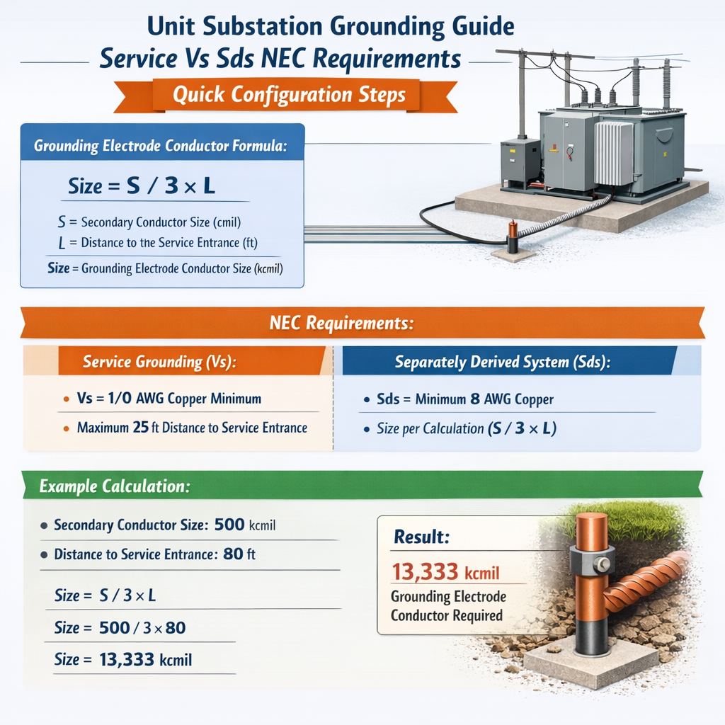
- 250.66 — Sizing of the GEC based on largest ungrounded service-entrance conductor or equivalent transformer secondary.
- 250.102 — Bonding jumpers and requirements for equipment grounding terminals and enclosures.
Fundamental grounding formulas and variable definitions
All formulas below are given in plain HTML; variables explained and typical values provided.
Ohm’s law applied to grounding
- V = voltage difference (volts). Typical: 120 V step potential limit for restricted areas; design targets often < 50 V.
- I = fault current (amperes). Typical: 5,000 A to 50,000 A in distribution systems; 10,000–30,000 A common for commercial.
- R = grounding system resistance (ohms). Typical target: < 5 Ω for buildings; substations target < 1 Ω depending on fault current and safety criteria.
Grounding electrode conductor minimum size (NEC 250.66 simplified)
Refer to NEC Table 250.66 for exact conductor sizes. Typical practical rule: GEC copper not smaller than 6 AWG for most commercial services; 4/0 AWG copper for very large services.
Approximate uniform-grid resistance estimate (simplified)
Rg ≈ ρ / (π × D × N)
- Rg = grid resistance (ohms); approximate for conceptual sizing only.
- ρ = soil resistivity (ohm·m). Typical: 10–1000 Ω·m (10 for wet clay, 100 for dry sandy soil).
- D = characteristic dimension (meters) — approximate grid dispersion length; use perimeter length or representative dimension.
- N = number of parallel conductors grouped by layout factor (dimensionless).
Note: IEEE Std 80 provides rigorous formulas and numerical methods (finite element, method of images) for precise Rg.
Touch and step potential simplified evaluation
E_step ≈ I_fault × R_surface / (2 × π × r)
- E_step = step voltage (volts) between two points separated by feet spacing across the surface.
- I_fault = fault current returning through soil (amperes).
- R_surface = surface layer resistivity factor (ohms per meter, derived from soil resistivity).
- r = radial distance from fault injection point (meters).
Typical mitigation target: ensure E_step < 50 V for hazardous areas, per IEEE guidance and local jurisdiction.
Grounding components and typical values
| Component | Typical Material | Typical Sizes | Typical Electrical Value / Note |
|---|---|---|---|
| Ground rod | Copper-clad steel | 5/8" × 8' (common), 3/4" × 10' (poor soil) | Resistance: 5–25 Ω per rod depending on soil; multiple rods parallel reduce resistance |
| Concrete-encased electrode (Ufer) | Reinforcing steel | 20 ft of rebar or mesh in foundation | Low resistance when concrete is present; often primary electrode for buildings |
| Ground grid conductor | Copper (bare) or copper-clad steel | #2 AWG to 4/0 AWG depending on fault current and grid layout | Grid spacing 3–10 m common; aim for grid resistance < 1 Ω for substations |
| Grounding electrode conductor (GEC) | Copper | 6 AWG to 4/0 AWG (NEC Table 250.66) | Size dependent on largest ungrounded conductor; protect from physical damage |
| Bonding jumpers | Copper | Depends on equipment; often same as equipment grounding conductor from NEC 250.122 | Continuity and low impedance required for fault clearing |
Quick configuration steps for unit substation grounding and SDS
Follow this checklist for initial configuration and commissioning.- Collect system data:
- Service voltage and configuration (e.g., 480Y/277 V, 3Ø, 4W).
- Transformer vector group and whether the transformer is a separately derived system (presence of neutral bonding switch).
- Available fault current at secondary and expected fault durations (from utility or short-circuit study).
- Soil resistivity profile (Wenner test preferred) and depth strata.
- Identify grounding electrode options per NEC 250.52 and bond all electrodes to a common grounding electrode system.
- Size GEC per NEC Table 250.66 correlating to largest ungrounded conductor or transformer secondary.
- Design ground grid using IEEE Std 80 procedures to limit step and touch potentials and achieve target Rg.
- Specify conductor sizes and return paths to ensure low impedance bonding to all metal enclosures (NEC 250.102).
- Install test points for ground resistance and ground potential rise (GPR) monitoring; perform commissioning tests.
- Document drawings, calculations, labeling, and training for operations and maintenance staff.
Detailed calculation workflows and examples
Example 1 — Unit substation grounding design for a 480 V transformer feeding a commercial facility
Scenario:- Pad-mounted 1500 kVA, 480Y/277 V transformer, secondary available three-phase fault current = 25,000 A symmetrical, clearing time 0.5 s (protective device).
- Soil resistivity test (Wenner) indicates uniform ρ = 100 Ω·m.
- Site constraints: 20 m × 10 m pad area available for ground grid.
- Target: Limit step and touch potentials per IEEE 80 criteria; achieve grid resistance Rg ≤ 0.5 Ω if possible; common electrode connection to SDS service electrode required.
- Use rule of thumb: choose grid conductor cross-section to handle prospective fault current for duration (skin effect negligible for seconds). For 25 kA for 0.5 s choose copper grid conductor of #2 AWG minimum, often larger for current sharing.
- NEC does not mandate grid conductor ampacity; rely on mechanical and thermal design per IEEE Std 80.
- Choose a square grid spacing of 3 m (10 ft) inside the pad with a perimeter conductor
approximate number of parallel conductors across the pad: along length 20/3 ≈ 6 runs, across width 10/3 ≈ 3 runs — total grid conductors ≈ 9 plus perimeter loop.
Rg ≈ ρ / (π × D × N)
- Let D = 10 m (approx. representative dimension), N = 9 parallel conductors, ρ = 100 Ω·m.
- Rg ≈ 100 / (π × 10 × 9) ≈ 100 / (282.74) ≈ 0.354 Ω.
Use Ohm’s law: V = I × R to estimate maximum GPR during fault.
- GPR_max = I_fault × Rg = 25,000 A × 0.35 Ω = 8,750 V.
- Critical: This is the maximum potential of the grid relative to remote earth; IEEE 80 provides procedures to convert GPR into local step and touch using equipotential zones and potential gradient calculations. Conservative check: ensure local equipotential bonding, step spacing, and insulating mats where personnel work near energized equipment.
- Provide at least two 8' copper-clad ground rods spaced a minimum of 6 m apart and bonded to the grid; expect per-rod resistance ~10–20 Ω in 100 Ω·m soil, so multiple rods reduce rod contribution.
- GEC size per NEC 250.66 for a 1500 kVA transformer secondary: largest ungrounded conductor area should guide; for 480 V system the conductor ampacity may be large; select GEC copper 4/0 AWG for robust connection (verify per Table 250.66).
- Perform fall-of-potential testing on the grid to verify Rg measured ≈ 0.35 Ω ± tolerance.
- Record soil resistivity data, test conditions, and as-built grid conductor sizes and locations.
- Grid: #2 AWG bare copper grid, spacing 3 m, perimeter conductor and ground rods bonded.
- GEC: 4/0 AWG copper per sizing decision and NEC Table 250.66 verification.
- Expected Rg ≈ 0.35 Ω; implement access control, equipotential bonding at cabinets, and insulating materials for service personnel working near live parts.
Example 2 — SDS (service disconnect switch) for 208Y/120 V service: GEC sizing and electrode selection
Scenario:- Building service: 800 A, 208Y/120 V, 3Ø, 4W; largest ungrounded conductor = 600 kcmil copper? For typical 800 A, maybe 600 kcmil AL or 600 MCM copper depending on installation. Use a conservative example: largest ungrounded conductor equivalent is 350 kcmil copper.
- Service equipment located at main SDS. Soil resistivity moderate; primary electrode is a Ufer (concrete-encased) with supplemental ground rods.
- NEC Table 250.66 requires GEC size based on largest ungrounded conductor.
- NEC Table 250.66 gives minimum sizes; for largest ungrounded conductor (e.g., 350 kcmil copper) the minimum GEC copper size often will be 4/0 AWG or larger. Confirm exact table entry for the edition of NEC applicable at the site.
- Provide a concrete-encased electrode (Ufer) connected to the rebar or embedded conductor if the building foundation complies — this is typically the primary electrode for building services.
- Supplement with two 8' rods spaced at least 6 ft apart, bonded to the Ufer.
- Bond the SDS enclosure neutral-to-ground per NEC 250.24 and connect the GEC at the SDS grounding electrode conductor lug (250.50).
- Ufer expected to have low resistance compared to rods; assume effective resistance contribution < 1 Ω in most concrete foundations.
- Rods in moderate soil may be ~10 Ω each; two rods in parallel ≈ 5 Ω, but when bonded to Ufer the combined system often yields < 2 Ω overall depending on soil and bonding.
- Determine that step potential around SDS area during a fault will be mitigated by equipotential bonding of metallic structures and signage restricting unqualified personnel.
- If SDS is in public access space, use additional electrodes or surface mats to reduce E_step below 50 V.
- GEC: copper 4/0 AWG (verify exact NEC table entry for the edition used).
- Electrodes: Ufer concrete-encased electrode bonded to rebar plus two 8' rods bonded to electrode system.
- Bond all service enclosures and metallic piping to the common electrode system per NEC 250.50 and 250.102.
Testing, commissioning, and verification procedures
Essential tests and acceptance criteria:- Soil resistivity tests (Wenner method) with multiple spacings and depths to establish layered resistivity profile.
- Fall-of-potential (three-point) test for grid resistance measurement. Acceptance per design target (e.g., Rg ≤ 0.5 Ω for substation grids, ≤ 5 Ω for typical building systems depending on design goal).
- Clamp-on ground resistance testing for individual rods and electrodes (useful for comparative verification, not absolute grid resistance).
- Continuity testing of bonding conductors and mechanical integrity checks of clamps and welded joints.
- Ground potential rise (GPR) computation and verification relative to protective device clearing time and fault current; ensure touch and step potentials meet IEEE thresholds.
Maintenance and periodic verification
- Inspect external bonding jumpers annually for corrosion, mechanical damage, and tightness.
- Repeat fall-of-potential testing every 3–5 years or after significant site changes (addition of structures, soil disturbance, major equipment changes).
- Update short-circuit study and grounding design calculations following system upgrades or changes in available fault current.
Common pitfalls and mitigation strategies
- Inadequate GEC sizing: Always cross-reference NEC Table 250.66 for the edition in force; oversize where practical for reliability.
- Assuming a single ground rod is sufficient: In medium-to-high resistivity soils, multiple rods or Ufer electrodes are typically required.
- Poor bonding continuity between unit substation and building SDS electrode systems: Ensure low impedance connections and direct bonding conductors without intermediate switching that could open the return path during faults.
- Ignoring rise of potential (GPR): Design only to Rg is insufficient — perform step/touch calculations per IEEE 80 to ensure local safety.
Summary and compliance recommendations
Unit substations and Service Disconnect Switch installations require an integrated approach combining NEC mandatory requirements with IEEE best practices for substation grounding. Key actions:- Follow NEC Article 250 for electrode selection and GEC sizing; consult local code authority having jurisdiction for edition-specific interpretation.
- Perform soil resistivity testing and use IEEE Std 80 to design a ground grid that meets step/touch potential criteria rather than relying on resistor targets alone.
- Document as-built grounding electrode systems, GEC sizes, and maintenance procedures; create a re-testing schedule and safety signage where required.
- NFPA 70 (NEC) — https://www.nfpa.org/NEC
- IEEE Std 80 — Guide for Safety in AC Substation Grounding — https://standards.ieee.org/standard/80-2013.html
- IEEE Std 142 — Grounding of Industrial and Commercial Power Systems — https://standards.ieee.org/standard/142-2007.html
- OSHA Electrical — https://www.osha.gov/electrical
- IEC 61936-1 — Power Installations Exceeding 1 kV AC — https://www.iso.org/standard/29538.html