La energía solar se destaca como una opción viable y sostenible para cubrir la demanda eléctrica actual.
Calcular cuántos paneles solares se necesitan requiere fórmulas precisas, valores de referencia y recomendaciones normativas.
Calculadora de Paneles Solares
Ejemplo vivienda: 10–20 kWh/día. Negocio pequeño: 30–60 kWh/día.
Ejemplo:
• Londres 4
• Bogotá 4.5
• Madrid 5
• México DF 5.5
• Atacama 7
Residencial común: 350–550 W. Comercial: 600+ W.
Estándar: 75–85 %. Premium: 90 % o más.
Aviso: este cálculo es orientativo y no sustituye un diseño fotovoltaico profesional.
Considere sombras, orientación, degradación, normativas y márgenes de seguridad antes de invertir.
Tabla de valores comunes para calcular número de paneles solares
A continuación se presenta una tabla extensa con valores comunes de consumo energético diario y el número aproximado de paneles solares requeridos, considerando paneles de 400 Wp y una radiación solar promedio de 5 kWh/m²/día.
| Consumo Diario (kWh/día) | Consumo Mensual (kWh/mes) | Energía Requerida Diaria (kWh/día) | Paneles de 400 Wp necesarios (aprox.) | Área aproximada requerida (m²) |
|---|---|---|---|---|
| 1 | 30 | 1.25 | 1 | 2 |
| 3 | 90 | 3.75 | 2 | 4 |
| 5 | 150 | 6.25 | 4 | 8 |
| 10 | 300 | 12.5 | 7-8 | 16 |
| 15 | 450 | 18.75 | 10-12 | 24 |
| 20 | 600 | 25 | 13-15 | 32 |
| 30 | 900 | 37.5 | 20-22 | 48 |
| 50 | 1500 | 62.5 | 31-35 | 80 |
| 100 | 3000 | 125 | 63-70 | 160 |
Nota: Se considera un factor de pérdidas del 20% y una eficiencia total del sistema del 80%. La radiación solar puede variar según la ubicación geográfica (entre 3 y 6 kWh/m²/día en Latinoamérica, según IRENA).
Fórmulas para calcular el número de paneles solares
Para determinar el número de paneles solares necesarios para cubrir una demanda energética, se utilizan varias fórmulas que tienen en cuenta la radiación solar, el consumo, la eficiencia del sistema y la potencia del panel.
1. Energía diaria necesaria
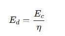
- E_d: Energía diaria necesaria del sistema (kWh/día)
- E_c: Consumo energético diario del usuario (kWh/día)
- η: Eficiencia total del sistema (valor típico: 0.75 a 0.85)
La eficiencia total considera pérdidas por conversión, temperatura, cableado, polvo, inversores y otros factores.
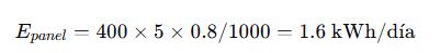
2. Producción de un panel solar diario

- E_panel: Energía generada por un panel por día (kWh/día)
- P_wp: Potencia pico del panel solar (W)
- H: Radiación solar promedio diaria (kWh/m²/día)
- PR: Performance Ratio o coeficiente de rendimiento (típico: 0.75 – 0.85)
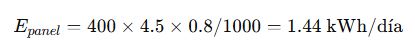
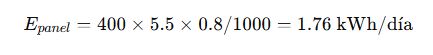
Por ejemplo, un panel de 400 Wp, con una irradiación de 5 kWh/m²/día y un PR de 0.8, produce:
3. Número de paneles necesarios
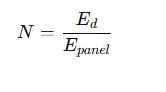
- N: Número de paneles necesarios
4. Área necesaria para instalación

- A: Área total necesaria (m²)
- A_panel: Área de un panel solar típico (aprox. 1.6 m² para 400 Wp)
Valores comunes de referencia
| Variable | Valor típico | Comentario |
|---|---|---|
| Consumo diario residencial | 3 – 15 kWh/día | Depende de electrodomésticos |
| Consumo comercial liviano | 20 – 50 kWh/día | Oficinas, tiendas |
| Panel solar típico | 350 – 450 Wp | Más comunes: 400 Wp |
| Radiación solar diaria | 3 – 6 kWh/m²/día | Varía por región |
| Eficiencia sistema (η) | 75% – 85% | Incluye pérdidas |
| Performance Ratio (PR) | 0.75 – 0.85 | Depende del diseño |
| Área por panel (400 Wp) | 1.6 – 2 m² | Con espacio mínimo |
Ejemplos de aplicación real
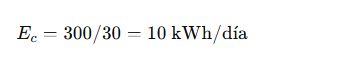
Caso 1: Vivienda unifamiliar en Bogotá, Colombia
Datos:
- Consumo mensual: 300 kWh
- Radiación solar promedio: 4.5 kWh/m²/día
- Paneles de 400 Wp
- PR = 0.8
- Eficiencia del sistema: 80%
Cálculos:
- Consumo diario:
- Energía diaria necesaria:

- Energía generada por panel:
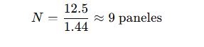
- Número de paneles:
- Área requerida:
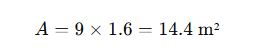
Resultado: Se requieren 9 paneles solares de 400 Wp y al menos 15 m² de techo disponible.
Caso 2: Pequeña tienda comercial en Monterrey, México
Datos:
- Consumo mensual: 900 kWh
- Radiación solar: 5.5 kWh/m²/día
- PR = 0.8
- Paneles de 400 Wp
- Eficiencia sistema: 80%
Cálculos:
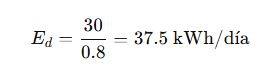
- Consumo diario:
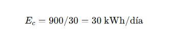
- Energía requerida:
- Producción por panel:
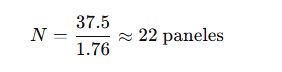
- Número de paneles:
- Área requerida:
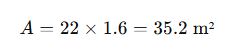
Resultado: Se necesitan 22 paneles de 400 Wp para cubrir completamente el consumo de esta tienda comercial.
Recomendaciones técnicas
- Evita el subdimensionamiento: Un error común es no considerar las pérdidas del sistema y la disminución de eficiencia con el tiempo.
- Considera baterías si el sistema es aislado: Para independencia total, calcula también almacenamiento en kWh.
- Verifica normativas locales: En Colombia aplica la Resolución CREG 030 de 2018, mientras que en México, la NOM-001-SEDE-2012 regula instalaciones fotovoltaicas.
- Consulta mapas solares oficiales: Como el Atlas Solar de Colombia o el Atlas Solar Global.
Factores que afectan el rendimiento del sistema fotovoltaico
Aunque las fórmulas básicas permiten una buena aproximación del número de paneles solares necesarios, diversos factores pueden alterar el rendimiento real del sistema. A continuación, se detallan los más relevantes:
1. Inclinación y orientación de los paneles
La inclinación óptima de los paneles solares depende de la latitud del sitio. En general:
- Para producción anual óptima:
Inclinación ≈ Latitud del lugar. - Para maximizar producción en invierno:
Inclinación ≈ Latitud + 10°. - Para verano:
Inclinación ≈ Latitud − 10°.
Además, los paneles deben orientarse al norte en el hemisferio sur y al sur en el hemisferio norte.
2. Sombras y obstrucciones
Las sombras causadas por árboles, edificios, antenas, etc., pueden reducir significativamente la producción. Se recomienda:
- Evitar sombras entre las 9:00 am y 3:00 pm.
- Instalar optimizadores de potencia si hay sombras parciales inevitables.
- Usar microinversores en vez de un inversor central.
3. Temperatura ambiente
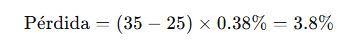
A mayor temperatura, menor eficiencia. Los paneles solares pierden rendimiento con el calor, típicamente 0.4% por °C sobre 25 °C. Se debe considerar el coeficiente de temperatura del panel.
Ejemplo:
4. Suciedad y mantenimiento
El polvo, hojas, nieve o excrementos de aves pueden reducir la eficiencia hasta un 10-20%. Se recomienda limpieza mensual en ambientes urbanos o polvorientos.
Ajustes para sistemas con almacenamiento (baterías)
En sistemas fotovoltaicos aislados o híbridos con almacenamiento, se deben tener en cuenta las siguientes fórmulas adicionales:
Energía almacenada necesaria
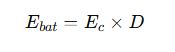
- E_bat: Energía a almacenar (kWh)
- D: Días de autonomía (típico: 1 a 3 días)
Capacidad de batería en Ah
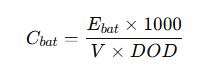
- V: Voltaje del banco de baterías (12, 24 o 48 V)
- DOD: Profundidad de descarga permitida (por ejemplo, 0.8 para baterías de litio)
Ejemplo:
Una vivienda con consumo de 10 kWh/día desea 2 días de autonomía, baterías a 48 V y DOD de 80%:

Herramientas recomendadas para cálculo preciso
- PVWatts Calculator – NREL (USA)
Herramienta oficial para estimación de producción solar según ubicación, ángulo, tipo de sistema y pérdidas. - Global Solar Atlas – Banco Mundial
Visualizador global de radiación solar media anual y mensual. - RETScreen – Natural Resources Canada
Software completo para análisis financiero y técnico de proyectos energéticos. - SAM – System Advisor Model (NREL)
Modelado avanzado de sistemas fotovoltaicos con simulaciones financieras y técnicas.
Errores comunes al dimensionar un sistema solar
1. Subestimar el consumo real
Muchos usuarios solo consideran electrodomésticos esenciales y omiten cargas como calentadores, hornos o aires acondicionados.
Consejo: Realiza una auditoría energética con herramientas como medidores inteligentes o apps de monitoreo.
2. No considerar crecimiento futuro
Un sistema p
uede volverse insuficiente en pocos años si se incrementan las cargas por compras futuras (ej. vehículo eléctrico, aire acondicionado, etc.).Consejo: Dimensiona con un 20–30% de holgura si el presupuesto lo permite.
3. Seleccionar paneles sin considerar disponibilidad local
No todos los paneles tienen el mismo rendimiento ni vida útil. Asegúrate de elegir modelos certificados (IEC 61215, IEC 61730).
Tabla comparativa de paneles solares por potencia
| Modelo comercial | Potencia (Wp) | Eficiencia (%) | Dimensiones (mm) | Área (m²) | Producción diaria estimada (kWh/día con 5 h sol) |
|---|---|---|---|---|---|
| Trina Solar TSM-400 | 400 | 20.2% | 2015 x 996 | 2.00 | 1.6 |
| Jinko Solar Tiger Neo 440 | 440 | 22.0% | 1762 x 1134 | 1.99 | 1.76 |
| Canadian Solar HiKu 455 | 455 | 20.8% | 2108 x 1048 | 2.21 | 1.82 |
| LONGi LR5-54HPH-415 | 415 | 21.2% | 1722 x 1134 | 1.95 | 1.66 |
Conclusiones prácticas y técnicas
El uso de una calculadora de número de paneles solares según demanda energética es clave para el diseño eficiente de un sistema fotovoltaico. Sin embargo, el resultado siempre debe ser validado por un profesional que tenga en cuenta las condiciones reales del sitio, las normativas locales y la proyección de consumo del usuario.
Adicionalmente, factores como el tipo de inversor, almacenamiento energético, sistemas híbridos y tarifas netas de energía deben integrarse en el análisis final para garantizar una inversión rentable y sostenible.