This expert-level article details turning radius definitions, measurement methods, geometric formulas, design values, and regulatory requirements.
It includes swept-path methods, overhang considerations, and two comprehensive real-world examples with step-by-step calculations.
Vehicle Turning Radius Calculator
Estimate curb-to-curb / wall-to-wall turning circle using wheelbase, steering angle, and overhangs.
Formulas used
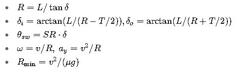
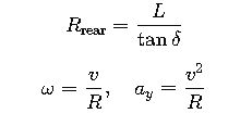
Bicycle model: R = L / tan(δ) (rear axle path).
Inner/outer rear wheel: Rinner = R − T/2, Router = R + T/2.
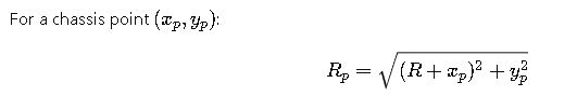
Outer front corner radius (curb-to-curb): Rofc = √((R + W/2)² + FO²).
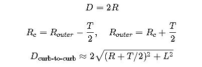
Curb-to-curb diameter: Dcurb = 2·Rofc.
Inner rear corner clearance: Rirc = √((R − W/2)² + RO²).
Wall-to-wall diameter (with margin c): Dwall = 2·(Rofc + c).
Inner/outer rear wheel: Rinner = R − T/2, Router = R + T/2.
Outer front corner radius (curb-to-curb): Rofc = √((R + W/2)² + FO²).
Curb-to-curb diameter: Dcurb = 2·Rofc.
Inner rear corner clearance: Rirc = √((R − W/2)² + RO²).
Wall-to-wall diameter (with margin c): Dwall = 2·(Rofc + c).
Curb-to-curb vs wall-to-wall
Curb-to-curb uses the outer front corner path with no extra clearance. Wall-to-wall adds a configurable margin to avoid scraping walls, posts, or curbs.
Why overhangs matter
Even if the axle path is tight, a long front overhang increases the outer corner arc (larger circle). A long rear overhang reduces the inner clearance radius.
Typical steering angles
Passenger cars ~30–38°, SUVs/pickups ~28–35°, city buses ~25–30°. Always use the actual angle/spec when available.
Quick reference: definitions and measurement conventions
- Turning radius (R) — the radius of the smallest circle the vehicle can negotiate at full steering lock. Some manufacturers and standards use radius, many publish turning circle or turning diameter (diameter = 2·R). The nomenclature is inconsistent in practice; always check whether the number is radius (m) or diameter (m).
- Curb-to-curb (kerb-to-kerb) — measurement that describes the distance needed for the wheels to make a U-turn (usually measured to the outermost wheel track). Wall-to-wall measures the full body sweep (including bumper overhangs) and is larger. Always state which method is used.
- Instantaneous center of rotation (ICR) — the kinematic point about which the vehicle is turning at any instant; used in geometric calculations and in the bicycle/kinematic model.
1) Extensive tables — common, authoritative turning-radius values (many vehicle classes & examples)
Table A — Representative passenger vehicles & small commercial vehicles (manufacturer / measured values)
| Vehicle (example) | Turning value | Type (R / diameter) | Measurement method |
|---|---|---|---|
| Smart ForTwo (2016) | 6.95 m | radius | curb-to-curb (manufacturer quoted: 22.8 ft turning circle) |
| Toyota Corolla (modern, typical configuration) | 5.2 m | radius (min turning radius — tyre) | manufacturer ‘min. turning radius – tyre’ |
| Toyota Camry (typical reported figure) | 10.9 m | diameter | curb-to-curb |
| Typical small passenger car (compact hatchback) | ≈5.0–6.0 m | radius | curb-to-curb (typical range) |
| Midsize sedan / small SUV | ≈5.5–6.5 m | radius | curb-to-curb (typical) |
Table B — Trucks, vans, buses, design vehicles (engineering / roadway design reference ranges)
| Vehicle / design vehicle | Typical turning radius (radius) | Typical turning diameter | Notes / design context |
|---|---|---|---|
| Delivery van / medium van (e.g., Ford Transit class) | ~6.0–7.5 m | 12–15 m | curb-to-curb typical for urban delivery vehicles |
| Pickup / light-truck (full-size) | ~6.0–8.0 m | — | depends strongly on wheelbase |
| 7.5-ton / medium truck | ~6.5–12 m | — | varies with wheelbase and axle set |
| City transit bus (rigid) | ~8.5–12 m | — | typical curb radii for city buses |
| Tractor-trailer (WB-50 / WB-62 / WB-67 type) | ~9–15 m (centerline) | turning diameter commonly >18 m | used for roadway/intersection design |
Table C — Tight/maneuverable industrial vehicles and specialized equipment
| Vehicle type | Typical outer turning radius (m) | Comment / where to use |
|---|---|---|
| 3-wheel electric forklift | ~1.3–2.0 m | very tight turning; used inside narrow aisles |
| Warehouse reach truck / narrow-aisle | ~1.0–2.5 m (effective) | specialized; depends on load length and stacking geometry |
| Large articulated bus | >7.5–12 m | measured to outer wheel path; swept path methods used for design |
2) All required formulas — geometric (kinematic), steering geometry, dynamics, swept-path
Notation / variables (used throughout)
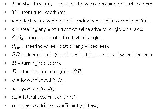
2.1 Kinematic bicycle model
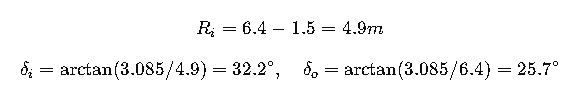
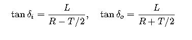
2.2 Ackermann geometry
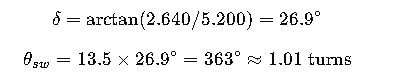
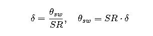
2.3 Steering ratio
2.4 Turning circle conversions
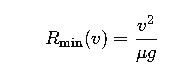
2.5 Dynamic limit