Proper tray and ladder sizing ensures safe, efficient, and maintainable electrical installations in all engineering applications.
IEC 61537 and IEC 60364 require evaluating tray dimensions based on cable quantity, type, and layout configuration.
Tray and Ladder Sizing – IEC
Common Tray and Ladder Sizes by Cable Capacity (IEC Reference)
Below are industry-standard tray and ladder dimensions used globally, based on typical installations and in alignment with IEC 61537:2016 and manufacturer catalogs. These tables serve as the starting point for sizing using calculator tools.
Table 1: IEC Common Ladder and Tray Dimensions
| Tray/Ladder Width (mm) | Usable Width (mm) | Typical Max Cable Quantity (3-core XLPE Cu, 4 mm²) | Typical Max Cable Quantity (3-core XLPE Cu, 10 mm²) |
|---|---|---|---|
| 50 | 40 | 6 | 4 |
| 100 | 90 | 14 | 8 |
| 150 | 140 | 21 | 12 |
| 200 | 190 | 28 | 16 |
| 300 | 290 | 42 | 24 |
| 400 | 390 | 56 | 32 |
| 600 | 590 | 84 | 48 |
| 800 | 790 | 112 | 64 |
Note: Quantities above are approximate and assume single-layer horizontal mounting without fill derating. For actual engineering practice, apply cable spacing, tray fill factors, and weight limits.
Tray Sizing Variables and Formulas According to IEC
The International Electrotechnical Commission (IEC) outlines clear guidelines in IEC 61537 for determining the appropriate tray or ladder based on mechanical strength, ventilation, electrical continuity, and fill capacity.
Formula 1: Cable Tray Fill Ratio

Where:
- Total Cable Area (mm²) = Sum of cross-sectional areas of all cables placed in the tray.
- Usable Tray Area (mm²) = Tray Width × Tray Height × Fill Factor
- Fill Factor: Recommended between 40% to 50% for proper ventilation (per IEC/NEC)
Typical values:
| Tray Height (mm) | Fill Factor (%) |
|---|---|
| 25 | 40 |
| 50 | 45 |
| 75 | 50 |
Formula 2: Cable Area Calculation

Where:
- D = External diameter of cable (mm)
- A_cable = Cross-sectional area (mm²)
This helps determine how many cables fit in the tray based on available area.
Formula 3: Total Weight of Cables per Meter

Where:
- n = Number of cables
- w = Weight per meter per cable (kg/m)
Weight calculation is essential for mechanical integrity of the ladder or tray over spans.
Formula 4: Maximum Span Load Verification
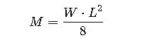
Where:
- M = Bending moment (Nm)
- W = Load per unit length (N/m)
- L = Span length (m)
Check this against manufacturer’s max permissible bending moment per tray type.
Formula 5: Voltage Drop Consideration (Optional but critical in sizing)
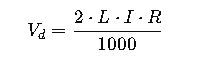
Where:
- V_d = Voltage drop (V)
- L = One-way cable length (m)
- I = Current (A)
- R = Resistance per km of cable (Ω/km)
Real-World Example 1: Data Center Cable Tray Design
Project Description: A 50-rack Tier III data center requires 300 CAT6 cables and 80 power cables (3-core, 6 mm²) routed over a 30-meter corridor using ladder trays.
Step-by-step Calculation:
1.Cable Diameters:
- CAT6: ~7 mm ⇒ Area = 38.5 mm²
- 6 mm² Cu Power Cable: ~11 mm ⇒ Area ≈ 95 mm²
2.Total Cable Area:
- CAT6: 300 × 38.5 = 11,550 mm²
- Power: 80 × 95 = 7,600 mm²
- Total = 19,150 mm²
3.Tray Area Needed (Fill Factor = 50%):

If using 75 mm height trays:

- Selection:
- Use a 600 mm wide × 75 mm deep tray.
- Add spacing, brackets every 2.5 m, and confirm mechanical limits with manufacturer.
Real-World Example 2: Industrial Plant – MV Cable Ladder Design
Scenario: A cement plant requires routing 20 medium-voltage armored cables (3-core, 50 mm²) over a 100-meter run on ladders mounted 4 meters above ground.
Input Data:
- Cable Diameter: 25 mm
- Cable Area: ~490 mm²
- Weight: ~2.5 kg/m
- Max Load per Ladder Section: 100 kg/m
Step-by-Step:
1.Total Area:

At 50% fill:

2.Mechanical Load:

3.Selection:
- Choose 200 mm wide ladder tray, 100 mm high
- Use galvanized steel ladder with mid-span supports every 3 m
- Confirm grounding continuity as per IEC 61537 section 10
Additional Considerations for Tray and Ladder Sizing
- Temperature Derating: Cable current ratings decrease at elevated temperatures. IEC 60287 provides guidelines.
- Fire Protection: Use fire-resistant trays or barriers in fire-rated zones.
- Seismic Zones: Bracket anchoring must follow local seismic codes (e.g., Eurocode 8).
- EMC Requirements: Maintain separation for power and data cables per IEC/TR 61000-5-2.
Cable Type and Fill Factor Reference
| Cable Type | Typical External Ø (mm) | Area (mm²) | Weight (kg/m) | Max in 200 mm Tray (50% Fill) |
|---|---|---|---|---|
| 3-core, 1.5 mm² Cu XLPE | 8 | 50.2 | 0.12 | 38 |
| 3-core, 10 mm² Cu XLPE | 13 | 132.7 | 0.40 | 14 |
| 3-core, 50 mm² Cu XLPE | 24 | 452.4 | 1.9 | 5 |
| CAT6 Ethernet | 7 | 38.5 | 0.05 | 52 |
Trusted References and External Resources
- IEC 61537: Cable Tray Systems – Official IEC standard
- IEC 60287: Electric Cables – Current-Carrying Capacity – Cable sizing under load
- IEC 60364-5-52 – Selection and erection of wiring systems
- Legrand Cable Management Guide (PDF) – Manufacturer-specific tray ratings