Transformer short-circuit current calculations ensure safety, reliability, and efficiency in electrical power systems. They determine maximum and minimum fault currents, guiding proper protection device selection and transformer resilience.
Transformer Short-Circuit Current Calculator
What formula is used?
Single-phase: Isc = (kVA × 1000) / (VLL × (Zt / 100))
What is transformer impedance?
Common Values for Transformer Short-Circuit Current Calculations
Below are some typical values used in transformer short-circuit current calculations:
| Parameter | Typical Value | Description |
|---|---|---|
| Transformer Impedance (%) | 4% – 6% | Represents the transformer’s impedance relative to its rated voltage. |
| System Voltage (Un) | 11 kV, 33 kV, 66 kV | Nominal system voltage. |
| Fault Duration (t) | 0.1 s – 2 s | Duration of the short-circuit fault. |
| Fault Location | Busbar, Transformer | Location where the fault occurs. |
| Grounding Type | Solid, Resistance | Type of grounding in the system. |
| X/R Ratio | 10 – 20 | Ratio of reactance to resistance in the fault path. |
Formulas for Transformer Short-Circuit Current Calculations
IEEE Methodology
The IEEE standard provides formulas to calculate the short-circuit current:
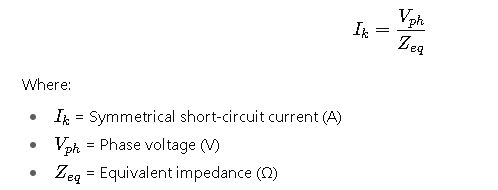
1.Symmetrical Short-Circuit Current (Ik):
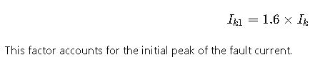
2.First Cycle Symmetrical RMS Current (Ik1):
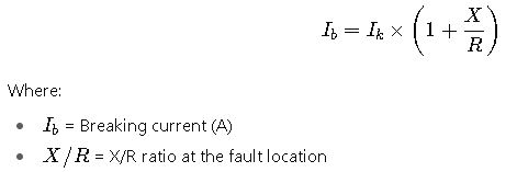
3.Breaking Current (Ib):
IEC Methodology
The IEC standard provides the following formulas:
1.Peak Short-Circuit Current (Ip):
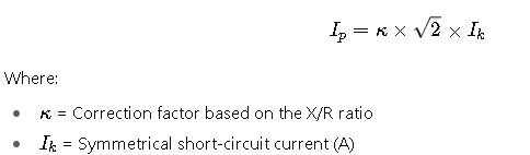
The correction factor κ is calculated as:
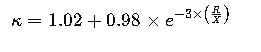
- R= Resistance (Ω)
- X= Reactance (Ω)
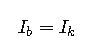
2.Breaking Current (Ib): For faults far from the generator:
For faults near the generator, the breaking current is calculated considering the decrement of the short-circuit current over time.
Real-World Examples
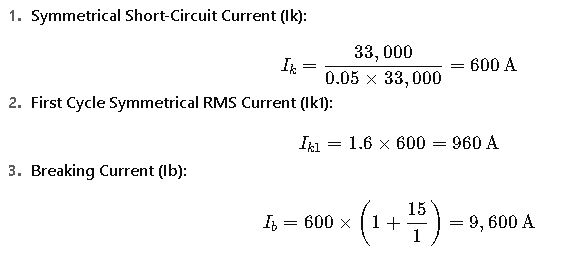
Example 1: Industrial Power System
Consider an industrial power system with the following parameters:
- Transformer impedance: 5%
- System voltage: 33 kV
- Fault location: Busbar
- X/R ratio: 15
Calculation:
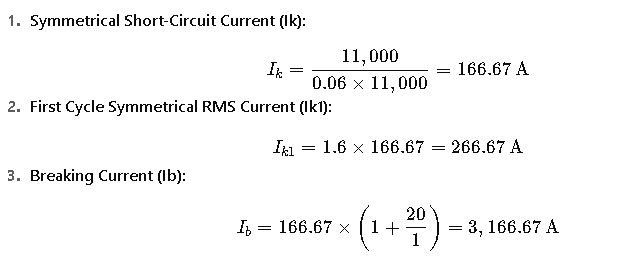
Example 2: Utility Distribution System
Consider a utility distribution system with the following parameters:
- Transformer impedance: 6%
- System voltage: 11 kV
- Fault location: Transformer
- X/R ratio: 20
Calculation:
Additional Considerations
- Impedance Tolerance: Transformers constructed to ANSI standards have a ±7.5% impedance tolerance. This tolerance can affect the short-circuit current calculations.
- Short-Circuit Duration: The duration of the short-circuit current is typically 2 seconds unless specified otherwise.
- Temperature Effects: The conductor resistance is specified for a reference temperature. The resistance for the actual temperature will be calculated using a correction factor.
Conclusion
Transformer short-circuit current calculations are vital for the design and protection of electrical power systems. By adhering to IEEE and IEC standards, engineers can ensure that transformers and associated equipment are adequately rated to withstand short-circuit conditions, thereby enhancing the safety and reliability of the power system.