Protecting transformers is critical for electrical system design, ensuring safe operation and avoiding dangerous overheating or failures. The National Electrical Code, mainly Article 450 with sections 240, 310, 725, establishes requirements for protection.
Transformer Protection Calculator — NEC Table 450.3
Calculate transformer full-load currents and maximum OCPD (primary & secondary) per NEC Table 450.3(B). Includes next-standard-device rounding and inrush guidance.
- NEC Table 450.3(B) governs maximum OCPD ratings to protect transformer windings (≤1000 V). Consult the table and notes for exact entries.
- Inrush currents can be many times rated current — use time-delay devices or inverse-time breakers when required.
- This calculator automates common Table 450.3 rules (primary-only = 125% with Note 1 rounding; primary+secondary allows larger primary % where applicable).
What percentages does NEC allow?
Why does rounding matter?
How should I pick time-delay protection?
1. Transformer Protection Requirements under NEC
The NEC specifies that transformer protection must:
- Prevent overheating and damage to the transformer windings.
- Protect against short circuits and overloads.
- Ensure coordination with upstream and downstream devices.
- Follow rules based on transformer size (kVA), voltage, and primary/secondary conductor ampacity.
The key NEC sections include:
- NEC 450.3: Overcurrent protection requirements.
- NEC 240.4: Conductor protection.
- NEC 310.16: Ampacity tables for conductors.
- NEC 250: Grounding and bonding.
2. Common NEC Values for Transformer Protection
The following tables summarize typical NEC transformer protection parameters. These values are representative and should always be confirmed against the latest NEC edition and manufacturer data.
Table 1 – Common Transformer Sizes and Full Load Current (FLC)
| Transformer kVA | Primary Voltage (V) | Secondary Voltage (V) | Full Load Current Primary (A) | Full Load Current Secondary (A) |
|---|---|---|---|---|
| 15 kVA | 480 | 208Y/120 | 18.0 | 41.6 |
| 30 kVA | 480 | 208Y/120 | 36.1 | 83.2 |
| 45 kVA | 480 | 208Y/120 | 54.2 | 124.9 |
| 75 kVA | 480 | 208Y/120 | 90.2 | 208.4 |
| 112.5 kVA | 480 | 208Y/120 | 135.4 | 312.6 |
| 150 kVA | 480 | 208Y/120 | 180.4 | 416.7 |
| 225 kVA | 480 | 208Y/120 | 270.6 | 625.1 |
| 300 kVA | 480 | 208Y/120 | 361 | 833.3 |
| 500 kVA | 480 | 208Y/120 | 601.7 | 1388.9 |
| 750 kVA | 480 | 208Y/120 | 902.5 | 2083.3 |
Formula used: FLC = (kVA × 1000) / (√3 × Voltage)
Table 2 – NEC Maximum Primary Overcurrent Protection (OCPD)
Based on NEC 450.3(B), depending on transformer primary current and rating.
| Transformer Size (kVA) | Primary FLC (A) | Max OCPD (125%) (A) | Next Standard Breaker/Fuse (A) |
|---|---|---|---|
| 15 | 18.0 | 22.5 | 25 |
| 30 | 36.1 | 45.1 | 50 |
| 45 | 54.2 | 67.8 | 70 |
| 75 | 90.2 | 112.8 | 125 |
| 112.5 | 135.4 | 169.3 | 175 |
| 150 | 180.4 | 225.5 | 225 |
| 225 | 270.6 | 338.3 | 350 |
| 300 | 361 | 451.3 | 450 |
| 500 | 601.7 | 752.1 | 800 |
| 750 | 902.5 | 1128.1 | 1200 |
Table 3 – NEC Secondary Conductor Protection (Typical)
| Secondary FLC (A) | Conductor Size (Cu, 75°C) | NEC Reference | Typical OCPD (A) |
|---|---|---|---|
| 41.6 | #8 AWG | NEC 310.16 | 50 |
| 83.2 | #3 AWG | NEC 310.16 | 100 |
| 124.9 | 1/0 AWG | NEC 310.16 | 150 |
| 208.4 | 3/0 AWG | NEC 310.16 | 225 |
| 312.6 | 500 kcmil | NEC 310.16 | 350 |
| 416.7 | 600 kcmil | NEC 310.16 | 450 |
| 625.1 | 900 kcmil | NEC 310.16 | 600 |
| 833.3 | Parallel 2 × 600 kcmil | NEC 310.16 | 800 |
| 1388.9 | Parallel 4 × 500 kcmil | NEC 310.16 | 1400 |
3. Formulas for Transformer Protection per NEC
3.1 Transformer Full Load Current (FLC)
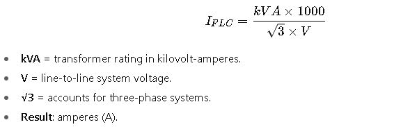
Typical FLC ranges:
- Small distribution transformer (15 kVA, 480 V): 18 A.
- Medium (150 kVA, 480 V): 180 A.
- Large (750 kVA, 480 V): 902 A.
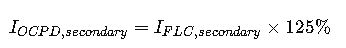
3.2 Primary Overcurrent Protection Device (OCPD)

- NEC 450.3(B) allows 125% for protection.
- Next standard breaker or fuse size is chosen (NEC 240.6).
3.3 Secondary Protection
- Conductors must handle ≥ 125% of secondary FLC.
- Conductor size per NEC 310.16.
3.4 Conductor Ampacity

Where:
- Aconductor = ampacity rating (from NEC Table 310.16).
- Factor of 125% ensures continuous load handling.
3.5 Short-Circuit Protection
For fuses and breakers, NEC allows:
- Up to 250% of primary FLC if protection is not sufficient at 125%.
- Always select the next lower standard rating if exact size unavailable.
4. Real-World Case Studies for Transformer Protection per NEC
Case Study 1 – 75 kVA Dry-Type Transformer (480 V to 208Y/120 V)
Scenario:
A commercial building requires a 75 kVA, 480 V to 208Y/120 V transformer to supply lighting and receptacle loads for an office floor. The engineer must design primary protection, secondary protection, and conductor sizing per NEC.
Step 1 – Transformer full load currents
From Table 1 above:
- Primary FLC = 90.2 A
- Secondary FLC = 208.4 A
These values are the foundation for selecting OCPDs and conductors.
Step 2 – Primary OCPD selection
According to NEC 450.3(B):
- Maximum protection is 125% of primary FLC = 112.8 A.
- Next standard breaker size = 125 A (NEC 240.6).
Thus, the primary breaker is 125 A at 480 V.
Step 3 – Primary conductor sizing
Per NEC 310.16 (75°C column, copper conductors):
- Required ampacity = 90.2 A × 125% = 112.8 A.
- Minimum conductor size = #1 AWG Cu (130 A at 75°C).
Step 4 – Secondary OCPD and conductors
- Secondary FLC = 208.4 A.
- Protection requirement = 208.4 × 125% ≈ 260 A.
- Next breaker size = 225 A or 250 A, depending on coordination.
For conductors:
- Required ampacity = 260 A.
- From NEC 310.16, 300 kcmil Cu (285 A at 75°C) satisfies this.
Step 5 – Grounding and bonding
- The transformer secondary must be grounded per NEC 250.30(A).
- Install a grounded conductor bond at the first disconnecting means.
Result:
- Primary breaker: 125 A, #1 AWG Cu conductors.
- Secondary breaker: 225–250 A, 300 kcmil Cu conductors.
- Transformer properly grounded and bonded.
This installation is fully NEC-compliant and protects both primary and secondary circuits.
Case Study 2 – 500 kVA Transformer for Industrial Plant (480 V to 208Y/120 V)
Scenario:
An industrial facility installs a 500 kVA, 480 V to 208Y/120 V transformer for a large production area. Because of high load and large conductor sizes, the engineer must use parallel feeders.
Step 1 – Transformer full load currents
From Table 1:
- Primary FLC = 601.7 A
- Secondary FLC = 1388.9 A
Step 2 – Primary OCPD
- NEC 450.3(B) allows 125% → 752 A.
- Next standard breaker size = 800 A at 480 V.
Step 3 – Primary conductors
- Required ampacity = 601.7 × 125% ≈ 752 A.
- From NEC 310.16, a single conductor cannot handle this.
- Solution: parallel sets of 500 kcmil Cu (380 A each).
- Two parallel runs per phase = 760 A → acceptable.
Step 4 – Secondary OCPD and conductors
- Secondary FLC = 1388.9 A.
- Protection requirement = 1388.9 × 125% = 1736 A.
- Next breaker size = 1750 A.
For conductors:
- No single conductor available for this ampacity.
- Choose parallel sets:
- 500 kcmil Cu = 380 A (75°C).
- Required sets = 1736 ÷ 380 ≈ 4.6.
- Round up → 5 parallel sets of 500 kcmil Cu per phase.
Step 5 – Grounding and coordination
- NEC 250 requires secondary neutral grounded at first disconnect.
- Coordination study must ensure the 800 A primary breaker trips only under major faults, while 1750 A secondary protection clears downstream issues.
Result:
- Primary breaker: 800 A, 2×500 kcmil Cu in parallel.
- Secondary breaker: 1750 A, 5×500 kcmil Cu in parallel.
- Proper bonding and grounding per NEC 250.
This system ensures safe and code-compliant transformer operation under heavy industrial loads.
5. Practical Considerations in Transformer Protection
Beyond formulas and code tables, engineers must account for real-world factors:
- Load diversity – Not all connected load runs simultaneously, but NEC sizing assumes full load.
- Temperature derating – Conductor ampacity from NEC 310.16 is based on 30°C ambient; hotter rooms require derating.
- Coordination studies – Protection devices must trip selectively to avoid full facility blackouts.
- Efficiency losses – Transformers have core and copper losses; protection must not allow overheating.
- Future capacity – Oversizing conductors and OCPDs slightly helps accommodate future expansions.
6. Common Mistakes in Transformer Protection Design
- Undersized conductors: Ignoring the 125% rule for continuous loads leads to overheating.
- Wrong breaker selection: Choosing standard sizes without checking NEC 240.6 leads to non-compliance.
- Skipping grounding: A floating neutral or unbonded system is a severe safety hazard.
- Improper parallel conductor installation: Conductors in parallel must be identical in length, material, and termination (NEC 310.10(H)).
- Not checking manufacturer data: NEC is a minimum standard; manufacturer thermal limits sometimes require stricter protection.