Designing and sizing transformer overcurrent protection under NEC ensures electrical system safety, reliability, and efficiency. NEC Articles 240, 450, and 310 define protective devices, conductors, and overload settings for transformer compliance.
Transformer Overcurrent & Overload Protection Calculator (NEC-based)
Compute transformer full-load currents and recommended maximum OCPD per NEC Table 450.3(B) (≤ 1,000 V). Use for design checks; verify with AHJ and equipment TCC.
How it works (formulas & NEC logic)
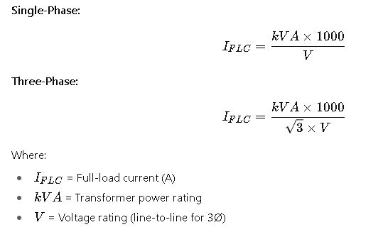
- Three-phase: I = (kVA × 1000) / (√3 × V). Single-phase: I = (kVA × 1000) / V.
- Table 450.3(B) percentages applied: primary-only → 125% primary; primary+secondary → 250% primary (max) and 125% secondary.
Why Transformer Overcurrent and Overload Protection Matters
- Prevent equipment damage: Transformers are costly assets, and improper protection can lead to insulation failure, overheating, or catastrophic failure.
- Ensure personnel safety: Properly sized protection devices minimize arc-flash energy and fault propagation.
- NEC compliance: The NEC prescribes minimum and maximum ratings for overcurrent protection, conductor ampacity, and overload factors.
- Operational reliability: Correct sizing ensures that protective devices trip under fault or overload conditions without nuisance tripping during normal inrush or transient events.
Key NEC References
- NEC 240 – Overcurrent Protection
- NEC 310 – Conductor Ampacity and Temperature Ratings
- NEC 450 – Transformers (including rules for protection)
- NEC 110 – General Requirements for Electrical Installations
Extended NEC-Based Tables for Transformer Protection
The following tables consolidate commonly used transformer sizes, full-load currents (FLC), conductor sizing, and maximum primary and secondary protection device ratings per NEC rules. These tables serve as a quick reference for engineers.
Table 1. Common Transformer kVA Ratings, Voltages, and Full-Load Current (Single-Phase)
| Transformer Size (kVA) | Voltage (V) | Full-Load Current (A) | NEC Reference Formula |
|---|---|---|---|
| 15 kVA | 240 V | 62.5 A | FLC = (kVA × 1000) ÷ V |
| 25 kVA | 240 V | 104.2 A | FLC = (25 × 1000) ÷ 240 |
| 37.5 kVA | 480 V | 45.1 A | FLC = (37.5 × 1000) ÷ 480 |
| 50 kVA | 480 V | 60.1 A | – |
| 75 kVA | 480 V | 90.2 A | – |
| 100 kVA | 480 V | 120.3 A | – |
| 167 kVA | 480 V | 200.6 A | – |
| 250 kVA | 480 V | 300.9 A | – |
| 500 kVA | 480 V | 601.8 A | – |
Table 2. Common Transformer kVA Ratings and Full-Load Current (Three-Phase)
| Transformer Size (kVA) | Voltage (V) | Full-Load Current (A) | NEC Formula |
|---|---|---|---|
| 30 kVA | 208 V | 83.4 A | FLC = (kVA × 1000) ÷ (√3 × V) |
| 45 kVA | 208 V | 125.1 A | – |
| 75 kVA | 480 V | 90.2 A | – |
| 112.5 kVA | 480 V | 135.4 A | – |
| 150 kVA | 480 V | 180.6 A | – |
| 225 kVA | 480 V | 270.8 A | – |
| 300 kVA | 480 V | 361.0 A | – |
| 500 kVA | 480 V | 601.8 A | – |
| 750 kVA | 480 V | 902.7 A | – |
| 1000 kVA | 480 V | 1203.6 A | – |
Table 3. NEC Maximum Primary Overcurrent Protection (OCPD) for Transformers (per NEC 450.3(B))
| Transformer Rating | Primary OCPD (Max % of FLC if ≤600V) | Notes |
|---|---|---|
| ≤ 600 V, FLC < 9 A | 167% (fuses), 167% (breaker) | May round up to next standard size |
| ≤ 600 V, FLC ≥ 9 A | 125% (fuses), 125% (breaker) | May increase to 250% if needed for inrush |
| > 600 V | 300% (fuses), 250% (breaker) | See NEC 450.3(A) |
Table 4. Typical Conductor Ampacity (Copper, 75°C, THWN/THHN Insulation) for Transformer Secondary
| Conductor Size (AWG) | Ampacity (A) | Typical Transformer kVA (480V 3Ø) |
|---|---|---|
| 3 AWG | 100 A | 75 kVA |
| 1/0 AWG | 150 A | 112.5 kVA |
| 3/0 AWG | 200 A | 150 kVA |
| 350 kcmil | 310 A | 225 kVA |
| 500 kcmil | 380 A | 300 kVA |
| 750 kcmil | 475 A | 500 kVA |
| 1000 kcmil | 545 A | 750 kVA |
Core Formulas for Transformer Overcurrent and Overload Protection
1. Full-Load Current (FLC)
2. Primary Overcurrent Protection (OCPD)

Typical factors per NEC 450.3(B):
- 125% for standard conditions (≤600 V)
- Up to 250% to handle magnetizing inrush current
3. Secondary Conductor Sizing

Where Factor = 125% (NEC 310 + 240 rules) for continuous loads.
4. Overload Protection (Optional)
Overload protection is typically provided by thermal devices inside the transformer or external protective relays. The formula:

5. Voltage Drop Consideration
For secondary conductors:
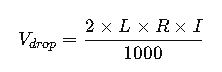
Where:
- L= Length of conductor (ft)
- R= Resistance per 1000 ft (Ω)
- I= Current (A)
Detailed Breakdown of Key Variables in Transformer Overcurrent and Overload Protection
Understanding each variable involved in transformer protection is critical for applying NEC requirements correctly. Below is a technical breakdown of the most relevant parameters used in calculations.
Transformer Power Rating (kVA)
- Definition: The rated capacity of a transformer, expressed in kilovolt-amperes (kVA).
- Typical Range: Small dry-type transformers for lighting panels are often 15 to 112.5 kVA, while large distribution transformers for industrial plants can exceed 1000 kVA.
- Practical Impact: The kVA directly determines the full-load current and thus the required ampacity of both primary and secondary protection.
Voltage Rating (V)
- Definition: The nominal operating voltage, either line-to-line or line-to-neutral.
- Common Values:
- Single-phase systems: 120/240 V
- Three-phase low-voltage systems: 208 V, 240 V, 480 V
- Medium-voltage systems: 2400 V, 4160 V, 13.8 kV
- Practical Impact: The selected voltage determines whether the NEC allows higher multipliers for OCPD sizing, especially above 600 V.
Full-Load Current (FLC)
- Definition: The current the transformer delivers at its rated capacity.
- Typical Values:
- A 75 kVA, 480 V three-phase transformer delivers about 90 A.
- A 500 kVA, 480 V three-phase transformer delivers about 602 A.
- Practical Impact: FLC is the baseline for sizing both conductors and overcurrent protection devices.
Overcurrent Protection Device (OCPD)
- Definition: Fuses or circuit breakers that protect the transformer and conductors from faults and short circuits.
- Common NEC Multipliers:
- 125% of FLC for typical cases at ≤600 V
- Up to 250% permitted when inrush current causes nuisance tripping
- At voltages >600 V, up to 300% may be allowed for fuses
- Practical Impact: Proper OCPD selection balances protection against overloads with avoiding nuisance trips during energization.
Secondary Conductor Sizing
- Definition: The ampacity of wires leaving the transformer secondary terminals.
- Common Wire Sizes:
- 3 AWG copper supports about 100 A
- 500 kcmil copper supports about 380 A
- Parallel runs are often used for very large transformers above 500 kVA
- Practical Impact: Undersized conductors can cause overheating and energy loss, while oversized conductors increase installation costs.
Overload Protection
- Definition: Protection that limits sustained overcurrent slightly above full-load but below fault current. Often implemented with thermal devices or relays.
- Common Practice: NEC does not mandate external overload devices for all transformers because most dry-type units rely on inherent temperature rise limits and optional thermal sensors.
- Practical Impact: In industrial plants, overload protection relays are often added for critical transformers to detect long-term thermal stress.
Voltage Drop
- Definition: The reduction in voltage from the transformer secondary to the load due to conductor resistance.
- Typical NEC Guidance: Limit voltage drop to 3% for feeders and 5% total for feeder plus branch circuit.
- Practical Impact: Excessive voltage drop reduces equipment efficiency and can cause premature failure in motors and sensitive electronics.
Real-World Case Studies
To illustrate how these variables are applied in practice, let’s analyze two detailed examples.
Case Study 1: Protecting a 75 kVA, 480 V Three-Phase Transformer for an Industrial Panel
Scenario:
An industrial facility installs a 75 kVA, 480 V three-phase dry-type transformer to supply a motor control center. The engineer must size the conductors and overcurrent protection in accordance with NEC.
Step 1 – Identify Full-Load Current
A 75 kVA transformer at 480 V three-phase delivers approximately 90 A.
Step 2 – Primary Protection Selection
- NEC requires a primary OCPD rated at 125% of FLC.
- 90 A × 125% ≈ 113 A.
- The next standard breaker size is 125 A.
- If nuisance tripping occurs due to inrush, NEC permits increasing up to 250%, which would allow up to 225 A.
Step 3 – Secondary Conductor Sizing
- The transformer’s secondary delivers 90 A.
- NEC requires sizing secondary conductors at 125% of load for continuous duty.
- 90 A × 125% = 113 A.
- A 1/0 AWG copper conductor rated 150 A (75°C insulation) is selected.
Step 4 – Secondary OCPD
- The NEC requires protection at 125% of FLC if installed at the secondary terminals.
- A 125 A breaker is suitable.
Final Design:
- Primary protection: 125 A breaker (with allowance to increase to 225 A if needed).
- Secondary conductors: 1/0 AWG copper.
- Secondary protection: 125 A breaker at the panel.
This configuration complies with NEC 450.3 and 310 ampacity tables while ensuring safe and efficient operation.
Case Study 2: Protecting a 500 kVA, 480 V Three-Phase Transformer for a Data Center
Scenario:
A data center requires a 500 kVA, 480 V three-phase liquid-filled transformer feeding a large distribution panel.
Step 1 – Identify Full-Load Current
A 500 kVA transformer at 480 V delivers about 602 A.
Step 2 – Primary Protection Selection
- NEC requires a primary OCPD of 125% of FLC.
- 602 A × 125% ≈ 753 A.
- The next standard size is 800 A.
- Due to inrush, NEC permits up to 250%, which would be 1505 A.
Step 3 – Secondary Conductor Sizing
- Secondary current = 602 A.
- At 125%, required ampacity = 752 A.
- A single set of conductors cannot handle this, so parallel runs are used.
- Two sets of 500 kcmil copper conductors, each rated ~380 A, provide a combined ampacity of 760 A.
Step 4 – Secondary OCPD
- NEC requires 125% protection at the secondary side.
- 602 A × 125% ≈ 753 A.
- An 800 A breaker at the distribution panel is chosen.
Final Design:
- Primary protection: 800 A breaker (option to increase if nuisance tripping occurs).
- Secondary conductors: Two parallel runs of 500 kcmil copper.
- Secondary protection: 800 A breaker feeding the data center panel.
This design balances NEC compliance with redundancy and efficiency required in data center environments.
Best Practices for Transformer Overcurrent and Overload Protection
- Always consult the latest NEC edition — the rules evolve every three years, and jurisdictional amendments may apply.
- Allow for transformer inrush current — especially for large dry-type units where nuisance tripping is common.
- Use parallel conductors for large transformers — when current exceeds single-conductor ampacity, parallel runs reduce size and cost.
- Consider harmonic currents — non-linear loads such as data centers and UPS systems increase heating and may require upsizing conductors.
- Implement protective relays — especially for medium-voltage transformers or mission-critical applications.
- Coordinate OCPDs with downstream breakers — to avoid cascading trips and maintain system selectivity.
- Factor in environmental conditions — high ambient temperatures, grouped conduits, or long runs affect conductor ampacity.