Accurate three phase cable sizing ensures safety, efficiency, and compliance across industrial electrical installations worldwide.
This article presents a comprehensive calculator methodology, standards references, worked examples, and practical guidance today.
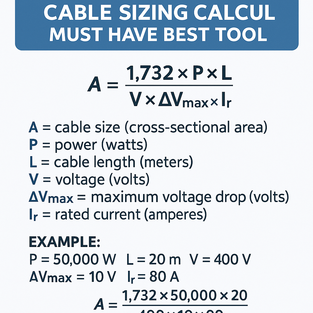
Three-phase cable sizing and voltage-drop calculator — engineering tool
Fundamental principles for three-phase cable sizing
Three-phase cable sizing is the engineering process that converts electrical load requirements and installation conditions into a conductor selection that meets thermal, mechanical and voltage-drop limits while complying with applicable standards.
Primary technical objectives
- Ensure conductor ampacity is greater than or equal to continuous load current considering derating factors.
- Keep voltage drop within permissible limits for equipment performance and coordination.
- Limit conductor temperature rise and avoid insulation degradation over the design life.
- Meet mechanical, short-circuit thermal and protection coordination requirements.
Inputs required for a three phase cable sizing calculator
To produce an accurate cable selection the calculator must accept a detailed set of inputs:
- Electrical: active power (kW), apparent power (kVA), current (A), nominal system voltage (line-to-line), power factor (cos φ), duty cycle, load diversity.
- Installation: conductor material (copper or aluminium), insulation type and temperature rating (e.g., XLPE 90°C), installation method (in free air, conduit, buried, duct), grouping (number of circuits together), depth, soil thermal resistivity.
- Environmental: ambient temperature, presence of radiant heat sources, elevation above sea level (altitude correction), exposure to sunlight.
- Mechanical: installation length (one-way), short-circuit withstand requirement (kA, duration), bending radius constraints.
- Regulatory: applicable standard/region rules (IEC/BS/NEC) and permissible voltage-drop limits (e.g., 3% or 5%).
Core formulas and their interpretation
All formulas below are presented in plain HTML with variable explanations and typical values. Use consistent units: power in watts (W) or kilowatts (kW), voltage in volts (V), current in amperes (A), resistance in ohms (Ω), reactance in ohms (Ω), length in metres (m).
1) Line current for a balanced three-phase load
Variable explanations and typical values:
- P = active power (W). Typical: small motor 7,500 W (7.5 kW), industrial load 75,000 W (75 kW).
- √3 = 1.73205 (constant for three-phase).
- V = line-to-line voltage (V). Typical low voltage: 400 V (Europe), 480 V (North America industrial).
- PF = power factor (decimal). Typical: 0.8–0.95. Motors often 0.85–0.95 under load.
- η = efficiency (decimal). Use 0.88–0.95 for motors; for resistive loads use 1.0.
2) Voltage drop for three-phase circuits (approximate)
Variables:
- I = line current (A).
- R = conductor resistance per kilometre (Ω/km) adjusted to operating temperature, or per metre (Ω/m). Typical copper R at 20°C: see table below.
- X = conductor reactance per kilometre (Ω/km) or per metre (Ω/m). Typical range for LV cables 0.08–0.2 Ω/km depending on conductor construction and separation (convert to Ω/m accordingly).
- cos φ and sin φ = power factor terms.
- L = one-way length in kilometres (km) consistent with R and X units (use metres with Ω/m). If using metres, convert R and X to Ω/m.
When using per-metre units: ΔV (V) = 1.732 × I × (R' cos φ + X' sin φ) × L(m) where R' and X' are in Ω/m.
3) Conductor temperature correction for resistance
Where:
- R_T = resistance at operating temperature T_op (°C).
- R_20 = resistance at 20 °C (Ω/km).
- α = temperature coefficient of resistivity (copper ≈ 0.00393 °C⁻¹, aluminium ≈ 0.0039 °C⁻¹).
- T_op = conductor operating temperature, typical 70°C for PVC or 90°C for XLPE rated cables under load.
Example: Copper 10 mm² R_20 = 1.83 Ω/km. At 90 °C: R_90 = 1.83 × [1 + 0.00393 × (90 − 20)] ≈ 1.83 × 1.275 ≈ 2.33 Ω/km.
4) Ampacity check (basic)
Where multiplicative derating factors (F_*) reduce allowed current. Typical factors provided in tables below.
Common conductor electrical properties and typical ampacity values
The following tables provide typical conductor resistance and ampacity values used by calculators as baseline references. Actual project selection must use the governing normative table for the region and installation method.
| Conductor (Cu) | Cross-section (mm²) | Resistance at 20°C (Ω/km) | Typical Ampacity (A) — single core in free air, 90°C insulation | Typical Ampacity (A) — 3 single cores in conduit, 30°C ambient |
|---|---|---|---|---|
| Copper | 1.5 | 12.1 | 18 | 15 |
| Copper | 2.5 | 7.41 | 24 | 21 |
| Copper | 4 | 4.61 | 32 | 29 |
| Copper | 6 | 3.08 | 41 | 36 |
| Copper | 10 | 1.83 | 57 | 52 |
| Copper | 16 | 1.15 | 76 | 70 |
| Copper | 25 | 0.727 | 101 | 92 |
| Copper | 35 | 0.524 | 125 | 115 |
| Copper | 50 | 0.387 | 150 | 135 |
| Copper | 70 | 0.268 | 195 | 175 |
| Copper | 95 | 0.193 | 229 | 205 |
| Copper | 120 | 0.153 | 256 | 230 |
| Copper | 150 | 0.124 | 300 | 270 |
| Copper | 185 | 0.100 | 350 | 315 |
| Conductor (Al) | Cross-section (mm²) | Resistance at 20°C (Ω/km) | Typical Ampacity (A) — single core in free air | Typical Ampacity (A) — 3 single cores in conduit |
|---|---|---|---|---|
| Aluminium | 16 | 1.91 | 55 | 48 |
| Aluminium | 25 | 1.24 | 76 | 68 |
| Aluminium | 35 | 0.85 | 95 | 85 |
| Aluminium | 50 | 0.641 | 125 | 110 |
| Aluminium | 70 | 0.443 | 160 | 142 |
| Aluminium | 95 | 0.320 | 200 | 180 |
| Aluminium | 120 | 0.255 | 230 | 208 |
| Aluminium | 150 | 0.206 | 270 | 240 |
| Aluminium | 185 | 0.170 | 325 | 290 |
Derating and correction factors
Derating factors must be applied cumulatively to establish the required conductor current capacity. The example factors below are typical; consult the applicable normative table for exact multipliers.
| Condition | Typical factor (F) | Notes |
|---|---|---|
| Ambient temperature 30°C (baseline) | 1.00 | Baseline for many tables |
| Ambient 40°C | 0.91 | Reduce ampacity to account for higher ambient |
| Ambient 50°C | 0.82 | High ambient |
| More than 1 circuit grouped (3-phase cables in same duct) | 0.8–0.9 | Depends on number of circuits and spacing |
| Buried in duct | 0.9 | Soil thermal resistivity and depth matter |
| Altitude > 1000 m | 0.95 | Reduce due to lower cooling by air (if applicable) |
Algorithm for a robust three-phase cable sizing calculator
- Input capture: Accept all electrical, installation and environmental inputs listed earlier.
- Load processing: Convert power values to line current using the three-phase current formula. For multiple loads provide cumulative and diversity application options.
- Apply derating: Multiply base ampacity by cumulative derating factors for installation conditions. Compute required ampacity = design current / (product of factors).
- Select candidate conductors: From conductor tables choose smallest conductor with base ampacity greater than required ampacity.
- Compute voltage drop: Use conductor R and X adjusted to operating temperature; calculate ΔV for the selected conductor and length.
- Verify against limits: If ΔV exceeds permissible limit, select larger conductor and repeat voltage-drop calculation until acceptable. If thermal/short-circuit limits are violated, escalate to next mechanical size or alternate installation method.
- Check short-circuit: Verify conductor withstand and protection device discrimination for prospective fault currents.
- Output: Provide final cable size, insulation type, expected conductor operating temperature, expected voltage drop (V and %), derating summary, and relevant normative references to justify selection.
Real case example 1 — Motor feed cable sizing (complete worked example)
Scenario: 75 kW, 400 V, 50 Hz three-phase induction motor, rated PF 0.9 at full load, motor efficiency η = 92% (0.92). Installation length from starter to motor = 50 m (one-way). Cable installation: 3-core in conduit in a cable tray with two other power circuits (grouping factor). Ambient temperature 35°C. Acceptable voltage drop ≤ 3% of 400 V = 12 V.
Step 1 — Calculate full-load current
Step 2 — Apply diversity and duty
Motor is continuous under heavy-duty duty, so use full current (no diversity). Design current = 131.2 A.
Step 3 — Derating factors
- Ambient 35°C: approximate temperature factor F_temp = 0.96 (typical table).
- Grouping: 3 circuits in same tray: F_group = 0.85 (typical, check standard table).
- Other factors: none significant. Total derating multiplier = F_temp × F_group = 0.96 × 0.85 = 0.816.
Step 4 — Select conductor from ampacity table
From the copper ampacity table above, a 35 mm² copper conductor has typical ampacity 125 A and 50 mm² is 150 A, 70 mm² is 195 A. The required ampacity 160.8 A exceeds 150 A (50 mm²), so choose 70 mm² copper to satisfy ampacity under derating.
Step 5 — Voltage drop check
Conductor resistance at 20°C for 70 mm² copper R_20 = 0.268 Ω/km = 0.000268 Ω/m. Assume reactance X' = 0.08 Ω/km = 0.00008 Ω/m (typical for closely spaced multicore). Adjust R for operating temperature: assume conductor operating temperature 90°C, α = 0.00393.
R_90 = 0.268 × [1 + 0.00393 × (90 − 20)] = 0.268 × 1.275 ≈ 0.342 Ω/km = 0.000342 Ω/m.
ΔV = 1.732 × 131.2 × 0.0003427 × 50 = 1.732 × 131.2 × 0.017135 = 1.732 × 2.247 ≈ 3.89 V
Percentage voltage drop = (3.89 / 400) × 100% ≈ 0.97% < 3% limit. Acceptable.
Step 6 — Final checks and documentation
- Cable selected: 70 mm² copper, 3-core, XLPE 90°C insulation (or equivalent), suitable armour if required.
- Voltage drop margin is acceptable. Ampacity satisfied after derating factors.
- Short-circuit withstand: verify fault current calculations with system impedance and cable short-circuit ratings as per IEC/NEC.
- Document selection with normative reference and calculation steps for audit.
Real case example 2 — Distribution feeder sizing with voltage-drop constraint
Scenario: A sub-distribution feeder supplies a mixed load with continuous apparent power S_total = 120 kVA at 400 V, PF = 0.95. One-way run length L = 120 m. Acceptable voltage drop = 3% (12 V). Installation: 3 single-core cables in conduit, ambient 30°C, insulation XLPE.
Step 1 — Convert to current
Step 2 — Derating
Three single cores in conduit: F_group = 0.7 (typical depending on installation); ambient 30°C baseline F_temp = 1.0. Required ampacity = 173.2 / 0.7 ≈ 247.4 A.
Step 3 — Select conductor
From copper table: 185 mm² gives 350 A, 150 mm² gives 300 A, 120 mm² gives 256 A. The required ampacity 247.4 A < 256 A so 120 mm² copper is marginally acceptable for ampacity.
Step 4 — Voltage drop for 120 mm²
R_20 for 120 mm² copper = 0.153 Ω/km = 0.000153 Ω/m. Assume X' = 0.08 Ω/km = 0.00008 Ω/m. Assume operating temperature 90°C → R_90 factor 1.275 → R' = 0.000153 × 1.275 = 0.0001951 Ω/m.
ΔV = 1.732 × 173.2 × 0.0002104 × 120 = 1.732 × 173.2 × 0.02525 ≈ 1.732 × 4.374 ≈ 7.57 V
Percentage voltage drop = (7.57 / 400) × 100% ≈ 1.89% < 3% — acceptable.
Step 5 — Final verification
- Ampacity: 120 mm² copper meets required ampacity after derating (256 A > 247.4 A margin small but acceptable).
- Voltage drop: acceptable at 1.89%.
- Recommendation: Document protective device rating and confirm short-circuit withstand for 120 mm². Consider increasing size to 150 mm² for operational margin if future load growth expected.
Short-circuit, protection coordination and mechanical considerations
Cable selection must also satisfy short-circuit thermal withstand (I²t) and mechanical constraints. Key checks include:
- Compare prospective fault current (kA) and fault duration with cable I²t capability (refer to IEC 60949 or national tables).
- Ensure protective device tripping curves clear cables before thermal damage for prospective faults—the protection setting must coordinate with cable ratings.
- Verify bending radius, sheath, and armouring suitable for installation environment and mechanical stress.
Regulatory references and authority documents
Use national and international standards to validate assumptions, derating tables, and acceptance criteria. Authoritative references:
- IEC 60364 — Electrical installations of buildings. General guidance on design and safety. (https://www.iec.ch)
- IEC 60287 — Electric cables — Calculation of the current rating. For ampacity calculation methodology. (https://www.iec.ch)
- IEC 60949 / IEEE 835 — Short-circuit current ratings and I²t assessment for conductors.
- BS 7671 (IET Wiring Regulations) — UK-specific wiring regulations with practical guidance on cable selection. (https://www.theiet.org)
- NFPA 70 National Electrical Code (NEC) — United States code for wiring methods and ampacity tables. (https://www.nfpa.org)
- EN 50525 — Electric cables — Common designations and constructional requirements for low voltage power cables.
Designers should consult the definitive, current edition of the applicable standard for binding numbers and tables; many standards are periodically updated.
Best practices and UX features for an effective three phase cable sizing calculator tool
To be the "must-have" best tool, implement features and UX that support engineering judgment, traceability and regulatory compliance:
- Input validation: unit-aware fields, min/max checks, and warnings for missing mandatory inputs.
- Profiles: pre-configured profiles for motors, lighting, heating and distribution with editable defaults.
- Derating matrix: interactive derating selection with visual explanation and links to normative sources.
- Step-by-step calculation trace: show intermediate values (calculated current, adjusted resistance, ΔV steps) for auditability.
- Multiple scenario comparison: allow quick "what-if" swaps of conductor material, length, and grouping to compare results.
- Exportable report: PDF/print-friendly summary with all inputs, assumptions, normative references and safety checks.
- Safety alerts: flag cases where voltage drop, ampacity, or short-circuit capability fail and recommend mitigations.
- Localization: support units (metric/imperial), regional standards selection (IEC/NEC/BS), and language translations.
- Versioning and traceability: record the standard edition and date used for tables in each calculation output.
Common pitfalls and mitigation strategies
- Underestimating derating: always apply grouping, ambient and burial corrections—use conservative multipliers where uncertainty exists.
- Ignoring operating temperature when computing resistance: adjust R for conductor temperature to avoid underestimating voltage drop.
- Choosing based only on ampacity: verify voltage drop and short-circuit withstand as equally critical criteria.
- Not documenting assumptions: provide full transparency in reports to enable validation by third parties.
- Using outdated normative tables: confirm the edition of the standard used and check for local amendments.
Validation, testing and certification considerations for tool developers
Engineering tools must be validated and maintained. Recommended validation steps:
- Cross-check outputs against manual calculations for a representative set of cases including resistive, inductive and motor loads.
- Compare results to manufacturer cable catalogues and accredited tables for ampacity and impedance.
- Implement unit tests that assert known outputs for canonical cases (e.g., a 75 kW motor at 50 m should match the worked example above within tolerance).
- Perform peer review by certified electrical engineers and maintain a change log for normative updates.
Summary of key selection workflow (engineering checklist)
- Gather load, installation and environment inputs.
- Compute line current and adjust for duty and diversity.
- Apply cumulative derating factors to determine required ampacity.
- Select smallest conductor with base ampacity greater than required ampacity.
- Calculate voltage drop using temperature-corrected R and appropriate X, verify against requirement.
- Confirm short-circuit withstand and protection coordination.
- Document outputs with normative references and assumptions.
Further reading and external authoritative resources
- IEC 60287 — Calculation of the current rating of cables: methodology and detailed rules. Seek the latest edition from IEC.
- IET Wiring Regulations (BS 7671) guidance notes and practical examples: https://www.theiet.org
- NFPA 70 (NEC) official code and handbooks for the United States: https://www.nfpa.org
- CIGRE and IEEE papers on cable ampacity and thermal modeling for detailed research literature.
- Manufacturer cable datasheets (e.g., Prysmian, Nexans, Southwire) for product-specific R, X and short-circuit limitations.
With consistent methodology, use of standards, conservative derating and full documentation, a three phase cable sizing calculator becomes an indispensable engineering tool for safe, efficient and code-compliant installations.