Accurate three-phase motor current estimation ensures safe design, reliable protection, and proper operation across diverse systems. NEC and IEC standards guide calculations, ensuring conductor ampacity, FLA determination, and compliance for global electrical installations.
Three-Phase Motor Current Calculator — NEC / IEC
Which formula does this use?
I = P_elec / (√3 × V_LL × PF). If you entered mechanical (shaft) power, the calculator converts to electrical input using the efficiency you provide.NEC guidance for conductor ampacity (informational)
Typical protection settings (informational)
Formulas & units
– If power input is in kW: use kW→W (×1000) before applying the three-phase formula.
– If service factor provided, final design current shown multiplies FLA by service factor.
Why Three-Phase Motor Current Calculation Matters
Three-phase motors represent more than 70% of industrial electrical load worldwide (IEA, 2021). Correct current calculation is crucial for:
- Sizing conductors according to NEC (Article 430) and IEC 60364 standards.
- Selecting circuit protection (fuses, MCCBs, thermal-magnetic breakers).
- Ensuring motor efficiency and reliability by operating within allowable limits.
- Compliance with safety regulations and preventing hazards such as overheating, insulation breakdown, or nuisance tripping.
Fundamental Formula for Three-Phase Motor Current
The basic formula for calculating the line current of a three-phase motor is:
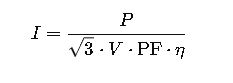
Where:
- I = Line current (A).
- P = Motor rated power (W or kW × 1000).
- V = Line-to-line voltage (V).
- PF = Power factor (dimensionless, typically 0.8–0.95 for motors).
- η = Efficiency (decimal, typically 0.85–0.97 for modern motors).
- √3 = 1.732 (constant for three-phase systems).
Notes on Variables:
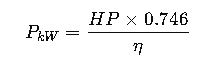
- Rated Power (P): Motors are commonly rated in kW or HP. Conversion:
- Voltage (V): Common IEC voltages include 400 V, 415 V, 690 V. In North America (NEC), 208 V, 230 V, 460 V, 575 V are frequent.
- Power Factor (PF): For standard induction motors ranges 0.80–0.92, for premium efficiency motors 0.93–0.96.
- Efficiency (η): Older motors 85–90%, IE3/IE4 premium efficiency >95%.
Extensive Reference Tables for Three-Phase Motor Current (NEC & IEC)
The following tables provide Full Load Current (FLA) values for common motor ratings according to NEC and IEC standard voltages.
Table 1: Three-Phase Motor Full Load Current (400 V IEC, PF=0.85, η=0.9)
| Power (kW) | Current (A) | Power (HP) | Current (A) |
|---|---|---|---|
| 0.75 kW | 1.5 A | 1 HP | 1.8 A |
| 1.5 kW | 3.0 A | 2 HP | 3.6 A |
| 2.2 kW | 4.3 A | 3 HP | 5.2 A |
| 3.7 kW | 7.3 A | 5 HP | 8.7 A |
| 5.5 kW | 10.7 A | 7.5 HP | 12.8 A |
| 7.5 kW | 14.6 A | 10 HP | 17.3 A |
| 11 kW | 21.4 A | 15 HP | 25.5 A |
| 15 kW | 29.2 A | 20 HP | 34.8 A |
| 18.5 kW | 36.0 A | 25 HP | 42.9 A |
| 22 kW | 42.9 A | 30 HP | 51.6 A |
| 30 kW | 58.5 A | 40 HP | 70.3 A |
| 37 kW | 72.1 A | 50 HP | 86.6 A |
| 45 kW | 87.7 A | 60 HP | 105.3 A |
| 55 kW | 107.0 A | 75 HP | 128.5 A |
| 75 kW | 146.2 A | 100 HP | 175.0 A |
| 90 kW | 175.5 A | 125 HP | 214.0 A |
| 110 kW | 214.0 A | 150 HP | 257.0 A |
| 132 kW | 257.0 A | 175 HP | 300.0 A |
| 160 kW | 311.0 A | 215 HP | 360.0 A |
| 200 kW | 388.0 A | 270 HP | 450.0 A |
Table 2: Three-Phase Motor Full Load Current (460 V NEC, PF=0.85, η=0.9)
| Power (HP) | Current (A) | Power (kW) | Current (A) |
|---|---|---|---|
| 1 HP | 1.25 A | 0.75 kW | 1.1 A |
| 2 HP | 2.5 A | 1.5 kW | 2.2 A |
| 3 HP | 3.7 A | 2.2 kW | 3.3 A |
| 5 HP | 6.2 A | 3.7 kW | 5.4 A |
| 7.5 HP | 9.3 A | 5.5 kW | 8.1 A |
| 10 HP | 12.4 A | 7.5 kW | 10.8 A |
| 15 HP | 18.6 A | 11 kW | 16.1 A |
| 20 HP | 24.8 A | 15 kW | 21.5 A |
| 25 HP | 31.0 A | 18.5 kW | 26.9 A |
| 30 HP | 37.2 A | 22 kW | 32.3 A |
| 40 HP | 49.6 A | 30 kW | 43.0 A |
| 50 HP | 62.0 A | 37 kW | 53.8 A |
| 60 HP | 74.4 A | 45 kW | 64.5 A |
| 75 HP | 93.0 A | 55 kW | 80.8 A |
| 100 HP | 124.0 A | 75 kW | 107.8 A |
| 125 HP | 155.0 A | 90 kW | 134.6 A |
| 150 HP | 186.0 A | 110 kW | 161.5 A |
| 200 HP | 248.0 A | 132 kW | 215.0 A |
| 250 HP | 310.0 A | 160 kW | 268.0 A |
| 300 HP | 372.0 A | 200 kW | 322.0 A |
NEC and IEC Guidelines for Motor Current Calculations
NEC (NFPA 70, Article 430):
- Conductor sizing: 125% of motor full load current.
- Overcurrent protection: Fuse/breaker size based on FLA and motor type (430.52).
- Locked-rotor current: Provided in NEC Tables 430.251(A/B).
IEC (IEC 60364 & IEC 60034):
- Current rating (In): Based on motor nameplate.
- Overload protection: Typically 115–120% of FLA.
- Coordination with short-circuit protection: Per IEC 60947-4-1.
Both standards emphasize using nameplate values whenever available, but calculators based on these formulas and tables are vital for design and preliminary sizing.
Practical Considerations in Motor Current Calculations
While formulas provide a theoretical foundation, practical application requires considering real operating conditions. Motors seldom run continuously at rated load; instead, they operate under varying loads, starting cycles, and environmental conditions. Standards such as NEC and IEC integrate safety margins to account for these variations.
Key aspects include:
- Service Factor (SF): Some motors are rated with a service factor (commonly 1.15). This allows short-duration overloads without overheating but must not be used as a continuous load.
- Temperature Rise: High ambient temperatures reduce motor efficiency and increase current. Both NEC and IEC guidelines recommend derating under elevated temperatures.
- Altitude: Motors operating above 1000 meters may require correction because air density affects cooling.
- Starting Current (Inrush): Standard squirrel-cage motors can draw 6–8 times FLA during startup. This impacts protection device selection and generator sizing.
Common Motor Current Ranges in Industry
To better understand real-world applications, here are some ranges of motor currents by industry:
- HVAC systems: Motors from 1–50 HP, currents typically 1–70 A.
- Pumps (municipal water plants): Motors 20–500 HP, currents 25–600 A.
- Compressors: Motors 50–300 HP, currents 60–400 A.
- Conveyors and material handling: Motors 5–100 HP, currents 6–120 A.
- Heavy industry (cement, mining, steel): Motors 500–5000 HP, currents up to several thousand amperes.
This shows why calculators aligned with NEC and IEC are essential: small variations in load or efficiency can change conductor and breaker sizes, impacting safety and cost.
Real-World Case Study 1: Municipal Water Pump Station
Scenario:
A municipality needs to install a 250 HP (≈186 kW) three-phase induction motor at 460 V, 60 Hz to drive a high-capacity water pump.
Conditions:
- Power factor: 0.9 (typical for pumps).
- Efficiency: 95% (IE3 motor).
- NEC compliance required.
Step-by-Step Application:
- Nameplate current check: The motor datasheet shows a nominal full load current of approximately 310 A.
- NEC adjustment: Article 430 requires conductor sizing at 125% of FLA, leading to 387.5 A ≈ 390 A minimum conductor ampacity.
- Overcurrent protection: Per NEC 430.52, a time-delay fuse may be sized at 175% of FLA, meaning 310 A × 1.75 = 543 A. A 600 A fuse would be selected.
- Practical adjustment: Engineers consider starting current, which can be 6 × FLA = 1860 A. The utility confirms that the local transformer can handle this inrush.
Result:
- Conductor sizing: 500 kcmil Cu (per NEC Table 310.16).
- Protection: 600 A time-delay fuse.
- Motor starter: NEMA Size 6, rated for 320 A continuous.
This case highlights how NEC guidelines bridge the gap between theoretical current and real-world safety margins.
Real-World Case Study 2: Conveyor System in a Manufacturing Plant
Scenario:
A European plant installs a 55 kW conveyor motor at 400 V, 50 Hz.
Conditions:
- Power factor: 0.85.
- Efficiency: 90%.
- IEC compliance required.
Application:
- Rated current from IEC table: Approximately 107 A at full load.
- IEC protection coordination:
- Overload relay set to 1.05 × FLA = 112 A.
- Short-circuit breaker coordinated with relay, selected at 160 A with appropriate trip curve (Type D for motor loads).
- Cable selection: IEC 60364 requires continuous current rating ≥ In. Using copper conductors, a 35 mm² cable rated 125 A is chosen.
Result:
- Motor operates efficiently under IEC rules.
- Protection ensures both overload and short-circuit safety.
- Energy efficiency is optimized by ensuring the motor runs close to rated load.
NEC vs IEC in Motor Current Calculations
Although NEC and IEC share the same physical principles, their application differs:
| Aspect | NEC (USA) | IEC (Global) |
|---|---|---|
| Conductor Sizing | 125% of FLA (Article 430) | In = FLA, derating factors apply |
| Overload Protection | Typically 115–125% of FLA | Typically 105–120% of FLA |
| Short-Circuit Protection | Fuse/breaker sized per tables (430.52) | Circuit breaker coordination per IEC 60947 |
| Locked-Rotor Current | NEC Tables 430.251(A/B) | Defined by motor manufacturer, typically 6–8 × FLA |
| Voltage Standards | 208, 230, 460, 575 V | 400, 415, 690 V |
| Focus | Safety margins, simplified tables | Flexibility, energy efficiency, international adaptability |
Both systems emphasize the motor nameplate data as the primary reference, but calculators become essential when sizing new installations or verifying compliance during design.
Industry Best Practices
- Always validate against the nameplate current. Calculators and tables provide estimates, but the nameplate is authoritative.
- Apply derating factors for temperature, altitude, and grouping of cables.
- Account for starting current when selecting protection and generator capacity.
- Use premium efficiency motors (IE3, IE4 or NEMA Premium) to reduce operating currents and energy costs.
- Cross-reference NEC and IEC when working in multinational projects to avoid mismatched conductor sizes and protection settings.