Improving power factor and reactive power compensation is critical for efficiency, reliability, and minimizing electrical costs. The Three-Phase Capacitor Bank Calculator, guided by IEEE standards, enables precise capacitor selection for diverse applications.
Three-Phase Capacitor Bank Calculator — kVAr Sizing
Compute required reactive power to correct power factor, per-phase sizing, capacitor current, and recommended unit count (IEEE-style formulas).
What does this calculator do?
IEEE-style formula used
Required reactive power (total) Qc (kVAr):
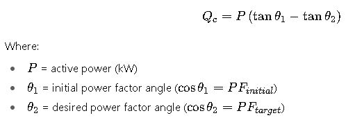
Qc = P · (tan φ₁ − tan φ₂).
Per phase (symmetrical): Qphase = Qc / 3.
Capacitor current per phase (A): Iphase = (Qphase·1000) / (Vphase·2π/ (2π)) → simplified: Iphase = Qphase·1000 / (Vphase·√3?) — see below for exact formula used in calculator.
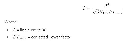
(Calculator uses: Iphase = (Qphase·1000) / (Vphase) for phase voltage; in three-phase line quantities we compute current using Q = √3·Vline·Iline → Iline = Qtotal·1000 / (√3·Vline))
Why W (kW) and not kVA?
Why connection type matters?
Extensive Reference Tables for Three-Phase Capacitor Bank Calculations
The following tables present the most commonly used values when sizing three-phase capacitor banks for power factor correction (PFC) and reactive power compensation in accordance with IEEE practice.
Table 1 – Reactive Power (kVAr) per Phase vs Line-to-Line Voltage
| Line-to-Line Voltage (V) | Capacitance per Phase (µF) | Reactive Power per Phase (kVAr) at 50 Hz | Reactive Power per Phase (kVAr) at 60 Hz |
|---|---|---|---|
| 220 | 130 | 3.1 | 3.7 |
| 380 | 75 | 4.3 | 5.2 |
| 400 | 70 | 4.4 | 5.3 |
| 415 | 65 | 4.6 | 5.5 |
| 440 | 60 | 4.8 | 5.8 |
| 480 | 55 | 5.0 | 6.1 |
| 600 | 40 | 5.6 | 6.8 |
| 690 | 35 | 6.3 | 7.5 |
| 1000 | 25 | 7.8 | 9.3 |
Table 2 – Common Capacitor Bank Sizes (Industrial & Utility)
| kVAr Rating | Typical Voltage (kV) | Number of Steps | Common Applications |
|---|---|---|---|
| 50 kVAr | 0.48 | 1–2 | Small commercial loads |
| 150 kVAr | 0.48 / 4.16 | 2–4 | Industrial motors, HVAC |
| 300 kVAr | 4.16 / 6.9 | 3–6 | Mining, medium-voltage feeders |
| 600 kVAr | 13.8 | 4–8 | Distribution substations |
| 1200 kVAr | 13.8 / 34.5 | 6–12 | Industrial plants, refineries |
| 2400 kVAr | 34.5 | 8–16 | Utility feeders, wind farms |
| 4800 kVAr | 69 | 12–20 | High-voltage substations |
Table 3 – IEEE Recommended Power Factor Targets
| Industry Sector | IEEE Target Power Factor | Typical kVAr Compensation Required (%) |
|---|---|---|
| Data Centers | ≥ 0.95 lagging | 15–20% of connected load kVA |
| Manufacturing Plants | ≥ 0.95 lagging | 20–25% of connected load kVA |
| Mining Operations | ≥ 0.92 lagging | 25–30% of connected load kVA |
| Utilities (Distribution) | ≥ 0.97 lagging | 10–15% of peak load kVA |
| Refineries | ≥ 0.95 lagging | 25–35% of connected load kVA |
Essential IEEE Formulas for Capacitor Bank Calculations
A capacitor bank calculator requires several interdependent formulas. Each is standardized by IEEE for use in reactive power compensation and power factor correction.
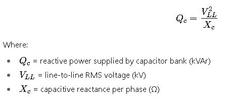
1. Reactive Power Supplied by a Capacitor Bank
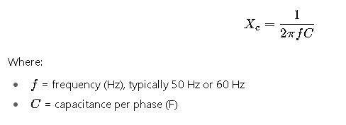
2. Capacitive Reactance
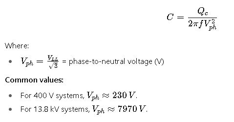
3. Capacitance Required per Phase
4. Power Factor Correction Requirement
5. Total Current per Phase after Compensation
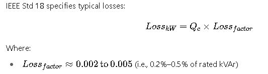
6. IEEE Loss Considerations for Capacitor Banks
Real-World Calculation Examples
Case Study 1 – Industrial Motor Load (Low-Voltage System)
Problem:
A manufacturing facility has a 480 V, 1000 kW induction motor load operating at 0.78 power factor lagging. The target PF is 0.95 lagging. Determine the required capacitor bank rating and new current after compensation.
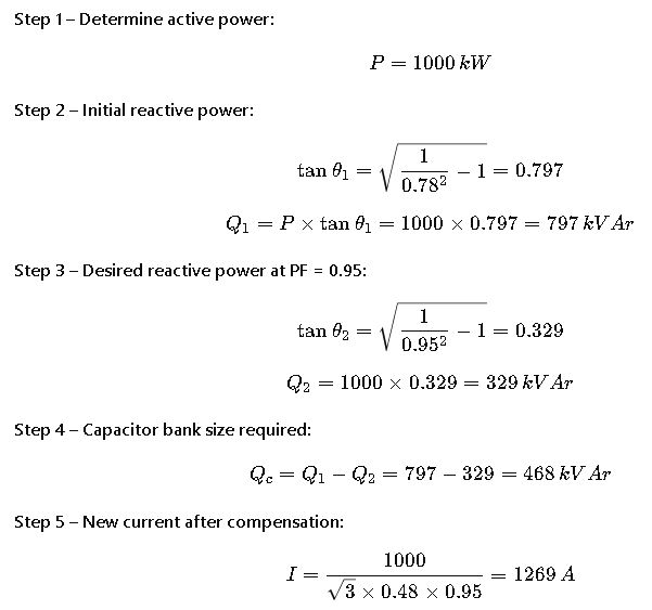
(Before compensation, current ≈ 1547 A. Reduction ≈ 18%.)
Case Study 2 – Utility Distribution Feeder (Medium Voltage System)
Problem:
A 13.8 kV utility distribution feeder supplies 10 MVA load at 0.85 lagging PF. The target PF is 0.98. Find required capacitor bank size.
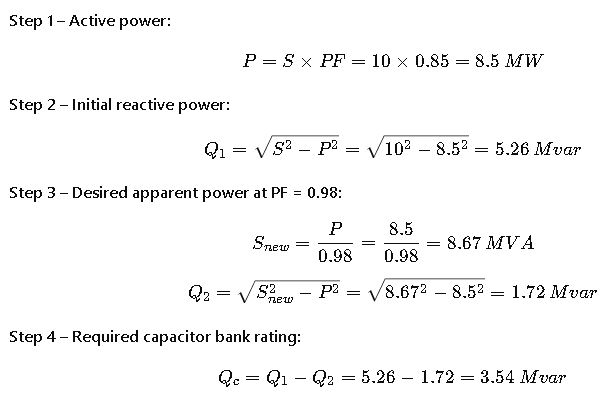
Thus, the utility requires a 3.6 Mvar capacitor bank at 13.8 kV, typically implemented as 3 × 1200 kVAr steps.
Harmonic Resonance and IEEE Standards
One of the most critical considerations in capacitor bank design is the interaction with system harmonics. Capacitors naturally reduce inductive reactive power, but they also shift the resonant frequency of the system.
- Harmonic amplification risk: When resonance occurs at or near a harmonic frequency (e.g., 5th, 7th, or 11th harmonic in industrial grids), capacitor banks can amplify distortion.
- IEEE Std 519-2014 establishes recommended harmonic distortion limits for both voltage and current. Utilities often impose contractual compliance with these limits, making capacitor design essential for power quality.
IEEE Recommendations for Harmonic Control
- Detuned capacitor banks: Incorporate series reactors (typically tuned to 189 Hz for 60 Hz systems, or 135 Hz for 50 Hz systems) to shift resonance below dominant harmonics.
- Filter banks: Combination of capacitors and reactors tuned to absorb specific harmonics. Common in steel plants, arc furnaces, and data centers.
- Capacitor derating: IEEE advises derating capacitors when harmonic content exceeds 5%, since heating and dielectric stress increase significantly.
Practical Selection of Three-Phase Capacitor Banks
When selecting a capacitor bank for power factor correction, engineers must balance reactive power needs, harmonic performance, and operational flexibility.
Step-Based vs Fixed Capacitor Banks
- Fixed banks: Provide a constant kVAr output, suitable for stable loads (e.g., lighting, constant motors).
- Automatic step banks: Use contactors or thyristor-based switches to add/remove steps as load fluctuates. Essential for industries with varying process loads.
Voltage Levels and Standards
- Low voltage (<1 kV): Common in commercial buildings, data centers, small factories. Prefabricated capacitor banks (e.g., 50–600 kVAr).
- Medium voltage (1–35 kV): Utilities, mines, industrial plants. Custom engineered, typically in ranges of 300–4800 kVAr.
- High voltage (>35 kV): Transmission substations, wind/solar farms. Banks exceed 10 Mvar and require protection relays, fusing, and surge arresters.
Maintenance Guidelines Based on IEEE 18 and IEEE 1036
Capacitor banks, though passive devices, require periodic inspection to maintain reliability. IEEE standards outline specific practices:
- Visual inspection:
- Swelling, bulging, or leaking oil-filled capacitors indicate dielectric failure.
- Check busbars, bolted joints, and grounding connections.
- Electrical testing:
- Measure capacitance drift: IEEE permits up to ±15% deviation from nameplate value.
- Insulation resistance (IR) should remain within acceptable limits (>1000 MΩ for LV units).
- Protection devices:
- Verify operation of fuses and overcurrent protection.
- Ensure surge arresters are not degraded by repeated transients.
- Thermal checks:
- Infrared thermography detects hot spots at connections.
- Overheated capacitors often result from harmonic overload.
Common Failure Modes of Capacitor Banks
Capacitor banks fail less frequently than rotating equipment, but when they do, consequences may include system instability or power quality deterioration.
- Dielectric breakdown: Caused by overvoltage, harmonics, or insulation aging.
- Overheating: From excessive harmonic current or poor ventilation.
- Unbalanced operation: A failed unit in a three-phase bank can shift reactive power balance, increasing system stress.
- Switchgear malfunction: Contactors or thyristor switches may fail under frequent switching, leading to inrush currents and transients.
IEEE 18 specifies endurance requirements for capacitor units, including overvoltage withstand tests, thermal cycling, and discharge performance.
Advanced Real-World Applications
Application 1 – Data Center Power Quality
Large hyperscale data centers often operate at near full load 24/7. Their uninterruptible power supply (UPS) systems and IT equipment introduce harmonics. To maintain PF > 0.95 and THD < 5% as required by IEEE 519:
- Engineers deploy automatic detuned capacitor banks of 400–1200 kVAr per floor.
- Reactors are sized to prevent resonance at the 5th and 7th harmonics.
- The result: reduced kVA demand charges, improved UPS efficiency, and compliance with utility harmonic limits.
Application 2 – Mining Operations at Medium Voltage
A copper mine in South America operates 6.9 kV crushers and ball mills with a combined demand of 15 MVA at PF = 0.82. Utility contracts impose a penalty if PF < 0.95.
- Engineers calculate the compensation required (~4.8 Mvar).
- Instead of a single fixed bank, a step-controlled capacitor system (6 × 800 kVAr units) is installed.
- Automatic controllers adjust compensation based on crusher cycles, avoiding over-correction during idle periods.
- The mine reduced annual utility penalties by over 12%, recovering project cost within 18 months.
Integration with Renewable Energy Systems
With the rise of wind and solar generation, capacitor banks play a growing role in grid stability:
- Wind farms: Capacitors provide reactive support for induction generators and grid code compliance.
- Solar PV plants: Capacitor banks offset inverter displacement PF, helping maintain a grid-level PF > 0.98.
- Hybrid systems: Capacitor banks often complement STATCOMs or synchronous condensers for dynamic VAR support.
IEEE 1547-2018 addresses interconnection of distributed energy resources (DERs), requiring adequate reactive power control—capacitor banks remain one of the most cost-effective methods.
Additional Reference Tables for Engineers
Table 4 – Typical Detuned Reactor Tuning Frequencies
| System Frequency | Reactor Tuning (Hz) | Harmonic Order Avoided |
|---|---|---|
| 50 Hz | 135 Hz | Avoids 3rd, 5th, 7th |
| 50 Hz | 189 Hz | Avoids 3rd, 5th, 7th |
| 60 Hz | 189 Hz | Avoids 5th, 7th, 11th |
| 60 Hz | 210 Hz | Avoids 5th, 7th, 11th |
Table 5 – IEEE Voltage Endurance for Capacitor Units (IEEE Std 18)
| Test Condition | Requirement |
|---|---|
| Continuous overvoltage (60 Hz) | Up to 110% of rated voltage |
| Short-duration (30 min/day) | Up to 115% of rated voltage |
| Transient overvoltage withstand | 180% of rated peak voltage |
| Discharge resistor performance | Discharge to ≤50 V in ≤5 minutes |