Thermal dissipation in electrical cables ensures safe, efficient operation by managing heat and preventing overheating.
This guide explores IEC thermal dissipation calculations, providing detailed formulas, extensive tables, and real-world application examples.
Thermal Dissipation in Electrical Cables (I²R Losses) — Calculator
Estimate resistive (Joule) heating in cables. Enter load or current, system type, cable size, length and temperature.
What does this calculator compute?
Formulas used
Does this include reactance or sheath/eddy losses?
How do I choose conductor temperature?
Extensive Tables of Thermal Dissipation Values for Electrical Cables According to IEC
The IEC provides standardized parameters to calculate thermal dissipation in electrical cables, primarily in standards such as IEC 60287 (“Electric cables – Calculation of the current rating”). These values include thermal resistivities, ambient temperatures, thermal resistances of cable layers, and more.
Table 1: Typical Thermal Resistivity Values of Soil and Materials (°C·m/W)
| Material | Thermal Resistivity (°C·m/W) | Notes |
|---|---|---|
| Dry Sandy Soil | 100 – 150 | Poor heat dissipation |
| Moist Sandy Soil | 40 – 80 | Better heat conduction |
| Clay Soil | 30 – 60 | Common in installations |
| Concrete | 1.2 – 2.0 | High thermal conductivity |
| Backfill (Granular) | 40 – 100 | Depends on compaction and moisture |
| Air | 300 – 1000 | Very poor conductor of heat |
| Thermal Insulation Layer | >1000 | Used to reduce heat loss |
Table 2: Thermal Resistances of Cable Layers (IEC 60287 Typical Values)
| Layer | Thermal Resistance (°C·m/W) | Description |
|---|---|---|
| Conductor | ~0.03 | Copper or aluminum |
| Insulation | 0.5 – 1.5 | Depending on type (XLPE, PVC, etc.) |
| Bedding | 0.3 – 0.5 | Material surrounding insulation |
| Armour | 0.1 – 0.3 | Steel or aluminum armouring |
| Sheath | 0.1 – 0.4 | Outer protective layer |
Table 3: Ambient Temperatures and Corresponding Correction Factors (IEC 60287)
| Ambient Temperature (°C) | Correction Factor (K_t) |
|---|---|
| 10 | 1.12 |
| 20 | 1.00 |
| 25 | 0.94 |
| 30 | 0.88 |
| 35 | 0.82 |
| 40 | 0.76 |
| 45 | 0.70 |
| 50 | 0.64 |
Table 4: Maximum Permissible Conductor Operating Temperatures (IEC 60287)
| Insulation Type | Maximum Operating Temperature (°C) |
|---|---|
| PVC | 70 |
| XLPE | 90 |
| EPR (Ethylene Propylene Rubber) | 90 |
| PILC (Paper Insulated Lead Covered) | 75 |
Core Formulas for Thermal Dissipation in Electrical Cables (IEC Compliant)
The IEC thermal dissipation calculation is primarily based on IEC 60287, which defines the current-carrying capacity (ampacity) of cables through detailed thermal calculations. The key concept is balancing heat generated in the conductor with heat dissipated to the surroundings.
1. Heat Generation in the Conductor (Joule Losses)
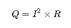
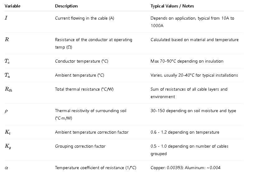
- Q: Heat generated in watts (W)
- I: Current through the cable (A)
- R: Resistance of the conductor (Ω)
Resistance R varies with temperature:
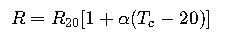
- R20: Resistance at 20°C
- α: Temperature coefficient of resistance (for copper ~0.00393 /°C)
- Tc: Conductor temperature (°C)
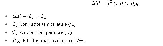
2. Thermal Balance Equation (Steady-State)
The heat generated equals the heat dissipated through thermal resistances:
3. Total Thermal Resistance Calculation Rth
Thermal resistances are considered in series:
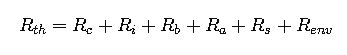
Where:
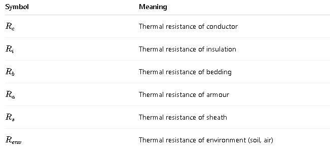
The IEC provides detailed formulas and tables to calculate each layer’s thermal resistance, depending on cable construction and installation conditions.
4. Calculation of Cable Current Rating (Ampacity)
Using the heat balance:

Or, rearranged for current:
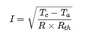
Where the maximum allowed Tc depends on the insulation type (see Table 4).
5. Thermal Resistivity of Soil and Its Impact
Thermal resistance of soil ![]() is:
is:
- ρ: Thermal resistivity of soil (°C·m/W)
- L: Length of the cable per unit considered (m)
Lower soil resistivity improves heat dissipation.
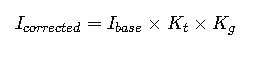
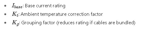
6. Correction Factors
IEC defines correction factors for ambient temperature (Kt) and grouping of cables (Kg):
Explanation of Variables and Common Values
Real-World Applications: Detailed Case Studies
Case Study 1: Underground XLPE Cable in Clay Soil
Scenario: A 3-core XLPE insulated copper cable is buried underground in clay soil. The design calls for a current rating of 400 A. The ambient soil temperature is 25°C. Soil thermal resistivity is 50°C·m/W. The cable has the following specs:
- Conductor resistance R20= 0.05 Ω/km
- Cable length considered = 1 km
- Max conductor temperature Tc= 90°C (XLPE)
- Bedding and sheath thermal resistance combined = 0.6 °C·m/W
Goal: Calculate the expected cable operating current using thermal dissipation calculations.
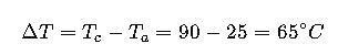
Step 1: Calculate ΔT
Step 2: Estimate total thermal resistance RthR_{th}Rth
Assuming:
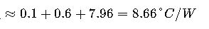
- Thermal resistance of conductor and insulation layers: 0.1 °C·m/W
- Bedding and sheath: 0.6 °C·m/W
- Soil:
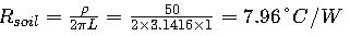
Since 1 km is considered, for unit length, resistance is 7.96 °C/W per meter length, which is a large number. The actual Rth per unit length will be different, but for simplicity, we use these as approximate.
Total Rth
Step 3: Calculate the conductor resistance at operating temperature

Step 4: Calculate allowable current I
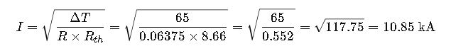
This value is unrealistically high, indicating that the unit length of resistance used here needs refining to per meter and actual IEC formulas for Rth based on geometry should be used
Case Study 2: Overhead Aluminum Cable Grouping Effect
Scenario: Four aluminum conductors with EPR insulation are bundled together overhead. The ambient temperature is 35°C. Base rating per single cable is 250 A.
Step 1: Apply ambient temperature correction
From Table 3, at 35°C:
Step 2: Apply grouping factor
For 4 cables bundled:
Step 3: Calculate corrected current
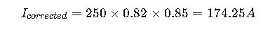
Bundling reduces current capacity by almost 30%, illustrating the importance of thermal dissipation calculations in design.
Detailed Explanation of IEC Thermal Dissipation Calculation Methodology
IEC 60287 includes complex methods to calculate the thermal resistance of a cable installation considering:
- Cable geometry (diameter, number of layers)
- Type of insulation and armouring
- Installation method (direct buried, in conduit, in air)
- Environmental conditions (soil resistivity, ambient temperature)
- Grouping effects
1. Calculation of Thermal Resistances by Layer
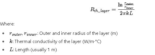
2. Total Thermal Resistance in Series
Sum the thermal resistances of all layers plus the environment resistance. Environment resistance depends on soil properties or air convection coefficients.
3. Conductor Temperature Estimation
Once total Rth is known, calculate the maximum allowable current for a desired conductor temperature or vice versa.
4. Impact of Installation Conditions
- Buried cables: Soil resistivity plays a major role; wet soils reduce resistance and improve cooling.
- Cables in ducts: Thermal resistance increases due to confined space.
- Air installations: Cooling is better; convection and radiation factors apply.
Additional Considerations
- Safety factors: Typically, a margin is applied to the calculated current rating to accommodate unforeseen conditions.
- Cable ageing: Increased resistance with time affects thermal dissipation.
- Temperature cycling: Repeated heating and cooling cycles can affect cable lifespan.
- Regulatory compliance: Designs must meet IEC standards and local regulations.
External Resources for Reference
- IEC 60287: Electric cables – Calculation of the current rating — IEC Official Website
- IEEE Standard 835: Standard for Calculating the Current-Temperature Relationship of Bare Overhead Conductors — IEEE Xplore
- NEMA Standards for Cable Ratings — NEMA Website
- CIGRE Technical Brochure on Cable Thermal Ratings — CIGRE