Accurate tank weight and load calculation is critical for mechanical, civil, and industrial engineering applications. This article provides formulas, tables, real-world examples, and standards to ensure safe and reliable tank design.
Tank Weight & Load Calculator — Estimate Empty Weight, Fluid Load & Total Mass
Instantly calculate tank shell weight, liquid weight and total loaded weight. Metric & Imperial support. Built for engineers, installers and procurement.
What does this calculator estimate?
Units and accuracy
Formulas used
Sphere: V = (4/3)·π·R³
Rectangular prism: V = W·H·L
Shell mass ≈ surface area · thickness · material_density (thickness in meters).
Hemispherical head area each = 2·π·R²; Ellipsoidal ≈ 2·π·R² (approx 0.5 ellipsoid).
Importance of Tank Weight and Load Calculation
The weight of a tank is not limited to its steel shell. It must include the following:
- Dead weight of the shell and roof (depending on thickness and material density).
- Weight of stored liquid or gas, including maximum filling level.
- Insulation and internal lining weight (if applicable).
- Nozzles, piping attachments, agitators, and fittings.
- Live loads and environmental loads, such as wind, snow, and seismic forces.
Proper load calculation ensures:
- Adequate foundation and soil capacity.
- Structural stability under operating and emergency conditions.
- Compliance with API 650, ASME Section VIII, Eurocode EN 1991, and other regulations.
Common Values for Tank Weight and Load
Below is a reference table of typical tank parameters and load factors used in preliminary engineering. These values can vary depending on design codes and manufacturers.
Table 1. Typical Density Values of Tank Materials and Fluids
| Material / Fluid | Density (kg/m³) | Density (lb/ft³) |
|---|---|---|
| Carbon steel (ASTM A36) | 7,850 | 490 |
| Stainless steel (304/316) | 8,000 | 499 |
| Concrete (normal) | 2,400 | 150 |
| Water (20 °C) | 1,000 | 62.4 |
| Diesel fuel | 830 | 51.8 |
| Crude oil (average) | 870 | 54.3 |
| Gasoline | 740 | 46.2 |
| Ethanol | 789 | 49.3 |
| Liquid ammonia | 682 | 42.6 |
| LNG (Liquefied Nat Gas) | 430–470 | 27–29 |
Table 2. Common Tank Geometries and Volume Formulas
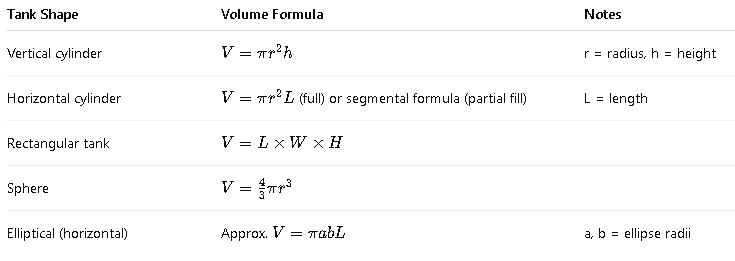
Table 3. Standard Tank Wall Thickness (per API 650 guidelines)
| Tank Diameter (m) | Typical Thickness (mm) | Notes |
|---|---|---|
| ≤ 5 | 6–8 | Light duty |
| 5–15 | 8–12 | Standard process tanks |
| 15–30 | 12–20 | Large storage tanks |
| 30–60 | 20–30+ | Heavy crude, LNG |
Core Formulas for Tank Weight and Load
Tank weight calculation involves shell weight, roof weight, bottom weight, and liquid load. Below are the standard formulas with detailed explanations.
1. Weight of Cylindrical Tank Shell
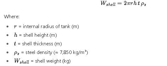
Typical values: For a medium-sized vertical steel tank (Ø 12 m, h = 10 m, t = 12 mm), shell weight may exceed 30 tons.
2. Weight of Tank Roof
For a flat roof (approximation):
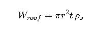
For a conical or dome roof, a shape factor is applied (typically 1.05–1.20 × flat area).
3. Weight of Tank Bottom Plate
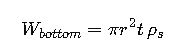
Bottom plates may include annular reinforcement rings (API 650) requiring increased thickness.
4. Weight of Contained Liquid
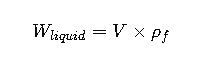
Where:
- V = tank volume at operating level (m³)
- ρf= fluid density (kg/m³)
This is typically the dominant load (90–95% of total weight).
5. Total Tank Operating Weight

Attachments include ladders, platforms, mixers, and insulation.
6. Foundation Load Distribution
Assuming uniform load:
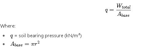
This must not exceed allowable soil bearing capacity per geotechnical survey.
Real-World Case Studies
Case Study 1: Vertical Water Storage Tank
Problem:
Design a 10 m diameter, 12 m height vertical cylindrical tank for water storage at 20 °C. Shell thickness = 12 mm, bottom plate = 12 mm, roof = conical (average thickness 10 mm).
Step 1. Tank geometry
- Radius r=5 m
- Height h=12m
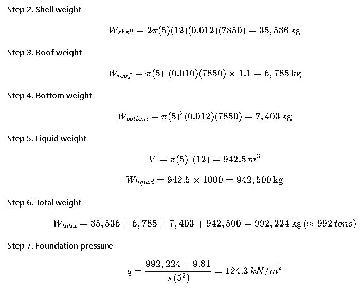
If soil capacity is ≥ 200 kN/m², foundation is adequate.
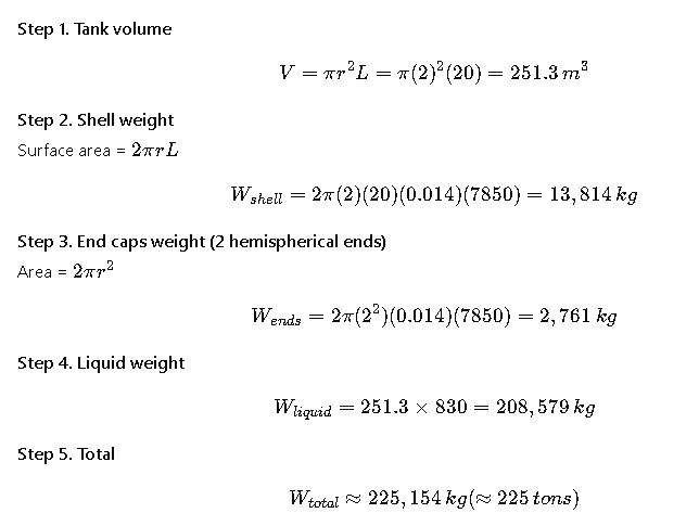
Case Study 2: Horizontal Diesel Tank
Problem:
Horizontal cylindrical steel tank, L = 20 m, D = 4 m. Wall thickness = 14 mm. Fluid = diesel (ρ = 830 kg/m³).
Normative References and Design Standards
- API 650 – Welded Tanks for Oil Storage (American Petroleum Institute)
- ASME Section VIII, Div. 1 – Pressure Vessel Code
- EN 14015 – European Standard for Welded Steel Tanks
- Eurocode EN 1991-1-4 – Wind Loads
- Eurocode EN 1998 – Seismic Loads
- AISC Steel Manual – Structural Steel Design
Authoritative references: