Electrical conduit systems ensure reliable, safe, and compliant wiring installations across residential, commercial, and industrial environments worldwide. Both NEC and IEC standards establish detailed requirements for conduit support, preventing sagging, stress, and dangerous code violations.
Support & Fastening System for Conduits Calculator — NEC & IEC
What this calculator does
Formulas & logic used
• For flexible conduits enforce close termination strap (12 in / 300 mm) if applicable.
• Compute effective spacing = S × safetyFactor; requiredSupports = ceil(runLength / effectiveSpacing) + ensure straps near each termination (if termination distance > allowed near distance an extra strap is counted).
• Positions are returned in run units, evenly distributed with first/last support within required termination distance. See code comments for exact rules.
Sources (NEC & IEC guidance)
Common Support Spacing Tables for Conduit Systems (NEC & IEC)
The following tables compile the most common support spacing values permitted by NEC and IEC. Values may vary depending on material (EMT, PVC, RMC, IMC, HDPE, etc.), trade size, and special conditions such as vertical runs or outdoor installations.
NEC Conduit Support Spacing Requirements (NFPA 70 – 2023 Edition)
| Conduit Type | Typical Trade Size (inches) | Maximum Spacing Between Supports (ft) | Notes |
|---|---|---|---|
| EMT (Electrical Metallic Tubing) | ½ – 1¼ | 10 ft | Must be secured within 3 ft of each outlet box, junction box, cabinet, or fitting |
| EMT | 1½ – 2 | 10 ft | Same rule applies |
| EMT | 2½ – 4 | 10 ft | Heavy runs may need closer spacing if subject to vibration |
| RMC (Rigid Metal Conduit – Steel) | ½ – 1¼ | 10 ft | Secure within 3 ft of termination |
| RMC | 1½ – 2 | 10 ft | – |
| RMC | 2½ – 6 | 10 ft | – |
| IMC (Intermediate Metal Conduit) | ½ – 6 | 10 ft | Similar to RMC |
| PVC (Rigid Nonmetallic Conduit, Schedule 40/80) | ½ – 1¼ | 3 ft | Thermal expansion joints may be required |
| PVC | 1½ – 2 | 3 ft | – |
| PVC | 2½ – 6 | 5 ft | Larger sizes can be spaced further apart |
| Flexible Metal Conduit (FMC) | ½ – 1¼ | 4.5 ft | Must be supported and secured frequently |
| FMC | >1¼ | 4.5 ft | – |
| Liquidtight Flexible Metal Conduit (LFMC) | ½ – 1¼ | 4.5 ft | Also within 12 in. of each termination |
| LFMC | >1¼ | 4.5 ft | – |
| Flexible Nonmetallic Conduit (FNMC) | ½ – 1¼ | 3 ft | Subject to damage if not properly secured |
| FNMC | >1¼ | 3 ft | – |
Key NEC Reference:
- NEC 2023, Articles 344 (RMC), 358 (EMT), 352 (PVC), 348 (FMC), 350 (LFMC), 356 (FNMC).
IEC Conduit Support Spacing Requirements (IEC 60364 and Related Standards)
IEC-based standards (adopted in Europe, Asia, Africa, and many other regions) define similar but sometimes stricter conduit support requirements.
| Conduit Type | Typical Trade Size (mm) | Maximum Spacing Between Supports (m) | Notes |
|---|---|---|---|
| Rigid Steel Conduit | 16–25 mm | 2.5 m | Must be secured within 0.5 m of box or termination |
| Rigid Steel Conduit | 32–50 mm | 3.0 m | – |
| Rigid Steel Conduit | 63–100 mm | 3.5 m | – |
| Rigid PVC Conduit | 16–25 mm | 0.9 m | Short spacing due to thermal sag |
| Rigid PVC Conduit | 32–50 mm | 1.2 m | – |
| Rigid PVC Conduit | 63–100 mm | 1.5 m | – |
| Flexible Conduit (Metallic) | 16–50 mm | 0.9 m | – |
| Flexible Conduit (Nonmetallic) | 16–50 mm | 0.6–0.9 m | Heavier derating for larger sizes |
| HDPE Conduit (Buried or Exposed) | 25–100 mm | 1.5–2.0 m | Must allow thermal expansion |
| Composite/Hybrid Conduits | 16–50 mm | 1.0–1.5 m | Country-specific IEC adoptions apply |
Key IEC References:
- IEC 60364-5-52: Electrical Installations of Buildings – Wiring Systems.
- IEC 61386: Conduit Systems for Cable Management.
Core Formulas for Conduit Support and Fastening
Although codes provide prescriptive maximum spacing values, engineers often need to calculate optimal support intervals based on mechanical stress, weight, and thermal expansion.
1. Maximum Support Span Based on Sag Limitation
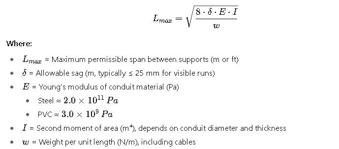
Interpretation:
- Heavier conduits with large diameters require shorter spans.
- Plastic conduits sag more due to lower stiffness, so closer spacing is mandatory.
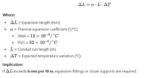
2. Support Spacing Based on Thermal Expansion
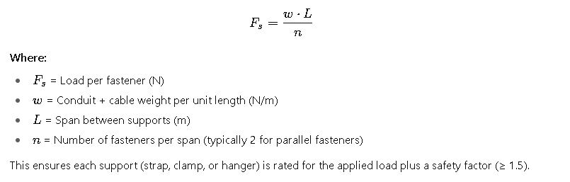
3. Support Load Calculation for Fasteners
Practical Considerations in Conduit Support Systems
While formulas provide a theoretical basis, real-world installations are influenced by material properties, installation environment, and code enforcement. Engineers and electricians must balance:
- Code compliance (NEC or IEC maximum spacing rules).
- Mechanical stability (avoid sagging or deformation).
- Thermal movement (especially in long PVC runs exposed to sun).
- Accessibility and aesthetics (straight alignment, consistent spacing).
- Load distribution (ensuring supports can handle weight of conduit plus cables).
- Environmental exposure (corrosion, vibration, seismic activity, or outdoor UV conditions).
Real-World Example 1: EMT Conduit in a Commercial Office (NEC)
Project Scenario:
An electrical contractor is installing EMT (Electrical Metallic Tubing) conduits for lighting and power circuits in a new office building in Chicago. The runs are horizontal, located above a suspended ceiling, and must comply with NEC requirements.
Given Conditions:
- Conduit type: EMT (per NEC Article 358).
- Trade size: 1 inch.
- Installation: Horizontal run, indoor, dry location.
- Expected temperature variation: ±10 °C.
- Span between junction boxes: 30 ft.
Step 1 – NEC Maximum Spacing
From NEC tables, EMT must be supported every 10 ft and within 3 ft of each termination.
- For a 30 ft run, minimum supports required:
- Start point: secured within 3 ft.
- Then supports every 10 ft: positions at 3 ft, 13 ft, 23 ft.
- End point: within 3 ft of termination (support at 27 ft).
Total = 4 supports minimum.
Step 2 – Practical Adjustment
The contractor chooses to reduce spacing to 8 ft for alignment with ceiling hangers and to improve aesthetics. This adds one extra support (at 19 ft).
Step 3 – Load Check
Each conduit section carries three #12 AWG copper conductors. Approximate weight:
- Conduit: 0.5 lb/ft.
- Cables: 0.3 lb/ft.
- Total: 0.8 lb/ft × 10 ft span = 8 lb per section.
Typical EMT straps are rated for ≥ 25 lb. Load check passes easily.
Final Installation:
- Supports installed at 3 ft, 11 ft, 19 ft, and 27 ft.
- Meets NEC and exceeds minimum safety.
- Aesthetic alignment achieved with ceiling grid.
Real-World Example 2: PVC Conduit in an Outdoor Industrial Plant (IEC)
Project Scenario:
A petrochemical plant in Spain is installing rigid PVC conduits outdoors on a cable rack for instrumentation wiring. The system must comply with IEC 60364 and account for thermal expansion due to sun exposure.
Given Conditions:
- Conduit type: Rigid PVC (IEC 61386 compliant).
- Trade size: 50 mm (≈ 2 in).
- Run length: 25 m.
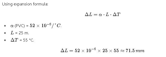
- Temperature variation: −10 °C to +45 °C (ΔT = 55 °C).
Step 1 – IEC Maximum Spacing
For PVC, IEC 60364 specifies:
- 1.2 m maximum spacing for 32–50 mm size.
- Supports required: 25 m ÷ 1.2 m = ~21 supports minimum.
Step 2 – Thermal Expansion
 Publicidad