Designing an effective roof drainage system ensures building integrity, protects structures, and maintains occupant safety efficiently. This guide explores detailed calculations, considerations, and industry-standard methods for accurately sizing roof drainage systems.
Roof Drainage System Calculator
How is the required flow calculated?
Chezy-Manning formula for gutters
Why do downspouts matter?
1. Roof Drainage System Calculation: Key Formulas and Variables
To accurately size a roof drainage system, it’s essential to understand the primary formula used:
1.1. Flow Rate Calculation
The flow rate (Q) is determined using the formula:
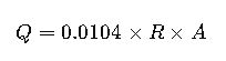
Where:
- Q = Flow rate in gallons per minute (GPM)
- R = Rainfall intensity in inches per hour
- A = Roof area in square feet
This formula helps in determining the volume of water that needs to be drained from the roof within a specific time frame.
1.2. Sizing Vertical Leaders
To determine the number of vertical leaders required, the total flow rate is divided by the capacity of a single leader:
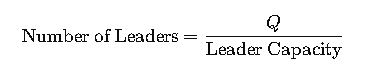
Where the leader capacity is based on the pipe size and slope, as detailed in manufacturer specifications.
1.3. Sizing Horizontal Storm Drains
For horizontal drains, the Manning’s equation is commonly used:
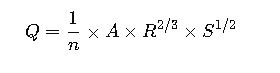
Where:
- n = Manning’s roughness coefficient
- A = Cross-sectional area of flow
- R = Hydraulic radius
- S = Slope of the drain
This equation helps in designing horizontal drainage systems that can efficiently carry the runoff to the discharge point.
2. Common Values and Assumptions
Understanding typical values and assumptions is vital for accurate calculations:
2.1. Rainfall Intensity (R)
Rainfall intensity varies based on geographic location and local climate data. For instance, areas prone to heavy rainfall may have higher intensity values. It’s essential to consult local meteorological data or building codes to obtain accurate values.
2.2. Roof Area (A)
The roof area is measured in square feet and should include all sections that contribute to runoff. This includes the main roof, overhangs, and any other surfaces that direct water towards the drainage system.
2.3. Leader Capacity
The capacity of a vertical leader depends on its diameter and slope. For example, a 4-inch diameter leader with a 1/8-inch per foot slope can handle approximately 144 GPM
2.4. Manning’s Roughness Coefficient (n)
The value of ‘n’ varies based on the material and condition of the pipe. Typical values are:
- PVC: 0.009
- Cast Iron: 0.013
- Concrete: 0.015
These values are used in the Manning’s equation to determine the flow capacity of horizontal drains.
3. Real-World Application Examples
3.1. Example 1: Commercial Building in a High-Rainfall Area
Scenario:
- Roof area: 50,000 sq ft
- Rainfall intensity: 4 inches/hour
Calculation:
- Flow rate: Q = 0.0104 × 4 × 50,000 = 2,080 GPM
- Assuming 6-inch diameter leaders with a capacity of 424 GPM each:
- Number of leaders = 2,080 / 424 ≈ 4.9, rounded up to 5 leaders
Conclusion:
Five 6-inch diameter vertical leaders are required to handle the runoff effectively.
3.2. Example 2: Residential Building in a Moderate Rainfall Area
Scenario:
- Roof area: 10,000 sq ft
- Rainfall intensity: 2 inches/hour
Calculation:
- Flow rate: Q = 0.0104 × 2 × 10,000 = 208 GPM
- Assuming 4-inch diameter leaders with a capacity of 144 GPM each:
- Number of leaders = 208 / 144 ≈ 1.4, rounded up to 2 leaders
Conclusion:
Two 4-inch diameter vertical leaders are sufficient for this residential building.
4. Additional Considerations
4.1. Secondary Drainage Systems
In areas with heavy rainfall or where primary systems may become overwhelmed, secondary drainage systems are essential. These systems should be designed to handle the same flow rate as the primary system to prevent water accumulation on the roof
4.2. Maintenance and Inspection
Regular maintenance and inspection of the roof drainage system are crucial to ensure its functionality. This includes checking for blockages, ensuring proper slope, and verifying the integrity of all components.
4.3. Compliance with Local Codes
Always ensure that the roof drainage system complies with local building codes and regulations. These codes provide guidelines for rainfall intensity values, drain sizing, and other critical factors.
5. Conclusion
Designing an effective roof drainage system requires a thorough understanding of hydrological principles, local climate data, and building codes. By accurately calculating flow rates, sizing components appropriately, and considering additional factors like secondary systems and maintenance, engineers can ensure the longevity and safety of the building.
For further reading and resources, consider consulting the following:
- International Plumbing Code – Chapter 11: Storm Drainage
- Manual for the Design of Roof Drainage Systems
- Roof Drain Sizing Method – Appendix A
By adhering to these guidelines and continuously updating knowledge with the latest standards, professionals can design roof drainage systems that effectively manage water runoff, protect building structures, and ensure occupant safety.