This guide explains retaining wall calculations with clarity, precision and practical engineering assumptions standards examples.
Focused on calculators, load cases and stability checks, engineers will find step-by-step computational workflows here.
Retaining Wall: Lateral Pressure and Basic Stability Calculator (Quick Technical Guide)
Design workflow and required inputs
A retaining wall calculator must follow a deterministic workflow to produce reliable outputs. Typical inputs include geometric parameters, soil properties, surcharge, groundwater conditions, seismic coefficients, material strengths, and drainage provisions.
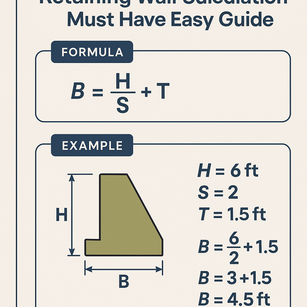
- Geometry: height (H), wall batter, toe and heel lengths, wall thickness, footing width (B).
- Soil: unit weight (γ), internal friction angle (φ), cohesion (c), backfill slope (β), groundwater table location.
- Loads: uniform surcharge (q), live loads, seismic pseudo-static coefficients (k_h, k_v).
- Materials: concrete unit weight, reinforcement, allowable bearing pressure, interface friction (δ).
- Safety targets: factors of safety for sliding (≥1.5 typical), overturning (≥2.0 typical), bearing (≥3.0 or per code).
Applicable theories for lateral earth pressure
Use an appropriate earth pressure theory depending on wall movement, wall friction, and backfill conditions. Leading methods:
- Rankine active and passive earth pressures (assumes vertical wall face and no wall friction δ = 0).
- Coulomb (general) earth pressure (considers wall friction δ, wall inclination, and backfill slope β).
- Mononobe-Okabe or pseudo-static methods for seismic loading (dynamic effects).
Key formulae for active and passive pressure coefficients
Active earth pressure coefficient (Rankine):
Passive earth pressure coefficient (Rankine):
Variables and typical values:
- φ = internal friction angle of soil (degrees). Typical values: 28°–36° for dense sands, 15°–25° for silty sands.
- Ka = active coefficient (dimensionless). Typical Ka for φ = 30° → Ka = 0.333.
- Kp = passive coefficient (dimensionless). Typical Kp for φ = 30° → Kp = 3.0.
| φ (deg) | Ka = tan^2(45° - φ/2) | Kp = tan^2(45° + φ/2) |
|---|---|---|
| 0 | 1.000 | 1.000 |
| 10 | 0.704 | 1.420 |
| 20 | 0.515 | 1.941 |
| 25 | 0.466 | 2.147 |
| 30 | 0.333 | 3.000 |
| 35 | 0.258 | 3.873 |
| 40 | 0.197 | 5.076 |
Lateral pressure distribution and resultant forces
For a homogeneous backfill with unit weight γ and height H, uniform surcharge q and active coefficient Ka, the resultant horizontal force per unit length (into the page) is:
Resultant horizontal force: P_a = 0.5 * γ * H^2 * K_a + q * H * K_a
Explanation of variables and typical values:
- P_a = total active lateral force per unit length (kN/m).
- γ = unit weight of backfill (kN/m³). Typical 17–20 kN/m³ for loose-dense soils; 18 kN/m³ common.
- H = retained height (m).
- K_a = active pressure coefficient (dimensionless) from Ka = tan^2(45° - φ/2).
- q = uniform surcharge (kPa = kN/m²). E.g. 10 kPa for light vehicle loading, 25–50 kPa for localized loads.
Location of resultant: for triangular distribution (no surcharge), the resultant acts at H/3 above the base. With surcharge, the combined resultant position x from base can be computed by summing moments of each component.
Stability checks: overturning, sliding, and bearing
Overturning calculation
Compute moments about the toe (or pivot). Define:
M_overturning = P_a * lever arm (distance from toe to resultant).
M_resisting = sum of weights × horizontal distance to toe + any passive pressure contributions × lever arm.
Factor of safety for overturning: FS_ot = M_resisting / M_overturning
Typical target: FS_ot ≥ 2.0 (consult local code).
Sliding calculation
Driving horizontal force: P_a (from earth pressures and surcharges).
Where W = total vertical load on base per unit length, δ_b = base friction angle (often δ_b ≈ 0.7φ or δ_b = φ for rough interfaces).
Factor of safety against sliding: FS_sl = R / P_a
Typical target: FS_sl ≥ 1.5 (static). For seismic pseudo-static use higher margins or limits as code requires.
Bearing capacity (Terzaghi simplified for strip footings)
Allowable ultimate bearing pressure q_ult (Terzaghi):
Variables:
- c = cohesion of soil (kPa). e.g. 0 for cohesionless sandy soils; 25–50 kPa for silty clays.
- q = vertical effective stress at footing base = γ' * Df (kPa).
- B = footing width (m).
- N_c, N_q, N_γ = bearing capacity factors depending on φ. See table below for typical values.
| φ (deg) | N_c | N_q | N_γ |
|---|---|---|---|
| 0 | 5.7 | 1.0 | 0 |
| 15 | 6.6 | 3.3 | 0.5 |
| 20 | 9.0 | 5.3 | 1.0 |
| 25 | 13.7 | 9.7 | 2.7 |
| 30 | 30.1 | 18.4 | 19.7 |
| 35 | 65.3 | 34.0 | 83.3 |
Seismic pseudo-static approach (calculator implementation)
For many calculators the pragmatic approach is the pseudo-static method: add a horizontal seismic body force proportional to the vertical stress using horizontal seismic coefficient k_h.
Integrate over the height H to get resultant seismic force:
Total lateral force to check against sliding/overturning:
Typical k_h values: 0.05 (low seismicity), 0.1–0.2 (moderate), 0.2–0.4 (high). Verify with local seismic design codes (e.g., ASCE 7, Eurocode 8).
Drainage and hydrostatic pressure effects
Pore water increases lateral loads. If the backfill is saturated and drainage is poor, hydrostatic pressure acts: p_w = γ_w * h_w, where γ_w ≈ 9.81 kN/m³.
If effective drainage is provided (drains, filter fabrics, weep holes), the design uses drained effective stress parameters and ignores hydrostatic buildup. If water cannot drain, superimpose hydrostatic pressure triangular distribution acting at H/3 with magnitude 0.5 * γ_w * H^2.
Material and unit weight tables
| Material | Typical γ (kN/m³) | Notes |
|---|---|---|
| Sandy backfill (loose) | 17 | Loose, low density |
| Sandy backfill (dense) | 19 | Well compacted |
| Lean clay | 17 | Medium stiffness |
| Soft clay | 15 | High compressibility |
| Concrete | 24 | Reinforced concrete |
| Water | 9.81 | Hydrostatic pressure |
Example 1 — Cantilever retaining wall (detailed calculation)
Problem statement: Design check for a reinforced concrete cantilever retaining wall retaining H = 3.0 m of granular backfill. Provide sliding, overturning and bearing checks.
Given:
- H = 3.0 m
- Backfill unit weight γ = 18 kN/m³
- φ = 30° (dense sand)
- No cohesion (c = 0)
- Surcharge q = 10 kPa
- Wall and footing geometry (assume base width B = 1.2 m, footing centroid position define toe length = 0.4 m)
- Concrete unit weight = 24 kN/m³. Assume wall stem and footing weights produce total vertical load W = 120 kN/m per meter length (example estimate).
- Interface friction δ_b = 2/3 * φ ≈ 20° (use δ_b = 20°)
P_soil = 0.5 * γ * H^2 * Ka = 0.5 * 18 * 3^2 * 0.333 = 0.5 * 18 * 9 * 0.333
Interpretation: FS_ot ~1.71 < desired 2.0 — requires geometry change (increase toe or weight) or reduced H.
Step 8 — Sliding check:Interpretation: FS_sl ~1.18 < 1.5 — unacceptable. Require shear keys, increase base width, passive resistance, or anchors.
Step 9 — Bearing check (simplified):Assume footing width B = 1.2 m; vertical stress due to W distributed uniformly: q_avg = W / B = 120 / 1.2 = 100 kPa
Assume φ = 30°, use bearing capacity factors (N_q ≈ 18.4, N_c ≈ 30.1, N_γ ≈ 19.7). For cohesionless soil c=0:
Apply factor of safety against bearing (e.g., 3): q_allow = q_ult / FS_bearing = 2052.8 / 3 ≈ 684 kPa; > q_avg (100 kPa). Bearing capacity is adequate.
Summary Example 1: Overturning and sliding inadequate for initial assumptions; bearing capacity adequate. Remediation: increase base width, add shear key, add passive toe extension, or include anchors.Example 2 — Anchored wall with pseudo-static seismic check
Problem statement: Check lateral loads and anchor design for a wall H = 6.0 m in moderate seismic zone. Use pseudo-static seismic coefficient k_h = 0.15.
Given:
- H = 6.0 m
- γ = 19 kN/m³ (compacted backfill)
- φ = 32° → Ka = tan^2(45° - 16°) ≈ tan^2(29°) ≈ 0.335
- Surcharge q = 0 kPa (assume no additional uniform load)
- Anchor located at z_anchor = 1.5 m above base; anchor provides horizontal resistance T per anchor.
- Spacing of anchors s = 2.0 m (along wall), per-meter calculations will consider 1.0 m width so influence of spacing later.
Implementation recommendations for a calculator
- Input validation: require units, convert consistently (e.g., kPa to kN/m², m, degrees).
- Modularity: separate modules for earth pressure, seismic, sliding, overturning, bearing capacity, drainage.
- Allow selection of earth pressure theory: Rankine, Coulomb (with δ and β inputs), Mononobe-Okabe or pseudo-static.
- Provide default values for novice users but require verification by a qualified engineer.
- Output detailed report: assumptions, step-by-step calculations, diagrams, and safety factor results.
Common mistakes and pitfalls
- Neglecting groundwater; hydrostatic pressures can dominate lateral loads if drains fail.
- Using Rankine where wall friction or wall inclination invalidates assumptions; use Coulomb for general cases.
- Not checking serviceability (excessive deformation or wall tilt) even if ultimate stability is acceptable.
- Ignoring surcharge effects from traffic and stored materials near the wall crest.
- Underestimating passive resistance due to probable non-engagement; sometimes conservative to assume limited passive contribution.
Verification and calibration against tests and standards
Always compare calculator outputs with code-specified factors and perform sensitivity analyses for key variables (φ, γ, q, water table). Validate against hand calculations for representative cases.
Normative references and authoritative resources
- Eurocode 7: Geotechnical design — Part 1: General rules. See: https://eurocodes.jrc.ec.europa.eu/showpage.php?id=138
- AASHTO LRFD Bridge Design Specifications — relevant sections on retaining structures and anchors. https://www.transportation.org
- FHWA (Federal Highway Administration) manuals on retaining walls and earth retention systems, e.g., FHWA-NHI-10-024. https://www.fhwa.dot.gov
- Mononobe-Okabe seismic earth pressure method: classic reference in geotechnical earthquake engineering; see research summaries at major universities and ASCE 7 commentary.
- Terzaghi, Peck & Mesri — Soil Mechanics fundamentals for bearing capacity relations.
Best practice UX features for the calculator
- Wizard-driven input with progressive disclosure of advanced options (e.g., Mononobe-Okabe vs. pseudo-static).
- Graphical representation of pressure diagrams, resultant location, and safety factor bar charts.
- Exportable calculation report with assumptions, units, and reference citations for compliance review.
- Interactive sensitivity sliders to show how changes in φ, γ, q, or k_h affect factors of safety in real time.
Checklist before issuing design
- Confirm geotechnical investigation data and in-situ unit weights and φ values.
- Confirm groundwater regime and seasonal fluctuations.
- Verify loads and surcharges including temporary construction loads.
- Confirm drainage design (filter, weep holes, geotextile) and maintenance.
- Perform global stability checks if site slopes exist; consider 2D or 3D analysis for complex geometry.
- Peer review by a qualified geotechnical engineer.
Closing technical remarks
Accurate retaining wall calculations require careful definition of soil parameters, correct selection of earth pressure theory, and conservative checks for sliding, overturning and bearing. Calculators should be used as design aids and never replace professional judgement and site-specific geotechnical investigation.
For code compliance always cross-reference local standards such as Eurocode 7, AASHTO, ASCE 7 and national annexes. Use the references listed above for detailed methodological rules, partial factors and seismic coefficients applicable to your jurisdiction.