Proper transformer protection is vital for safety, efficiency, and NEC compliance in electrical system design applications. The NEC establishes requirements for primary and secondary OCPDs, ensuring fire prevention, equipment reliability, and continuous service.
NEC Transformer Protection Calculator — Primary & Secondary OCPD Sizing (Table 450.3(B))
Enter transformer rating and voltages. The calculator shows full-load currents (FLA) and recommended maximum overcurrent protective device (OCPD) sizes following NEC Table 450.3(B). It also offers the next standard OCPD sizes per NEC 240.6(A) where Note 1 permits.
| Item | Value |
|---|
Why these percentages?
Note about rounding to next standard OCPD
Conductor guidance
Importance of Transformer Protection Sizing
Transformers represent a substantial investment in any power distribution system. Improper protection can result in:
- Overheating leading to insulation failure.
- Coordination issues with upstream/downstream devices.
- Reduced system reliability and downtime.
- Code violations and potential safety hazards.
The NEC (primarily Article 450 and related tables such as Table 450.3(B)) defines maximum protection limits while also allowing practical adjustments for coordination, efficiency, and operational safety.
Core NEC References for Transformer Protection
The following NEC sections provide the backbone for primary and secondary protection sizing:
- NEC 450.3(B): Maximum rating or setting of OCPDs for transformers 600 V and less.
- NEC 450.3(A): Requirements for transformers over 600 V.
- NEC 240.6(A): Standard ampere ratings for overcurrent devices.
- NEC 240.4(B): Rounding up to the next standard OCPD size (commonly called the next size rule).
- NEC 240.21(C): Secondary conductor protection rules.
Common Primary and Secondary Protection Values
The NEC allows two approaches to transformer protection:
- Primary-only protection (when secondary protection is not required under specific conditions).
- Primary plus secondary protection (most common in practical applications).
The following extensive tables summarize typical values for transformers 600 V and below according to NEC Table 450.3(B), expanded with practical FLA values and common breaker sizes.
Table 1. Maximum Primary OCPD Rating for Transformers ≤ 600 V (Per NEC 450.3(B))
| Transformer kVA | Primary Voltage (V) | Primary Full Load Current (FLA) | Max Primary Protection (% of FLA with Primary Only Protection) | Max OCPD Size (A, Rounded to Standard) |
|---|---|---|---|---|
| 15 | 480 | 18.0 A | 250% | 45 A → 50 A |
| 30 | 480 | 36.1 A | 250% | 90 A |
| 45 | 480 | 54.2 A | 250% | 135 A → 150 A |
| 75 | 480 | 90.2 A | 250% | 225 A |
| 112.5 | 480 | 135.4 A | 250% | 338 A → 350 A |
| 150 | 480 | 180.5 A | 250% | 451 A → 450 A |
| 225 | 480 | 270.8 A | 250% | 677 A → 700 A |
| 300 | 480 | 361.0 A | 250% | 902 A → 1000 A |
| 500 | 480 | 601.7 A | 250% | 1504 A → 1500 A |
| 750 | 480 | 902.5 A | 250% | 2256 A → 2250 A |
Note: FLA values calculated using formula explained later. Next standard OCPD sizes taken from NEC 240.6(A).
Table 2. Maximum Secondary Protection Rating (Per NEC 450.3(B))
| Transformer kVA | Secondary Voltage (V) | Secondary Full Load Current (FLA) | Max Secondary Protection (% of FLA) | Max OCPD Size (A, Rounded to Standard) |
|---|---|---|---|---|
| 15 | 208/120 | 41.7 A | 125% | 52 A → 60 A |
| 30 | 208/120 | 83.4 A | 125% | 104 A → 110 A |
| 45 | 208/120 | 125.1 A | 125% | 156 A → 175 A |
| 75 | 208/120 | 208.5 A | 125% | 261 A → 300 A |
| 112.5 | 208/120 | 312.7 A | 125% | 391 A → 400 A |
| 150 | 208/120 | 417.0 A | 125% | 521 A → 600 A |
| 225 | 208/120 | 625.5 A | 125% | 782 A → 800 A |
| 300 | 208/120 | 834.0 A | 125% | 1042 A → 1100 A |
| 500 | 208/120 | 1390.0 A | 125% | 1738 A → 1750 A |
| 750 | 208/120 | 2085.0 A | 125% | 2606 A → 2600 A |
Key Formulas for Transformer Protection Sizing
To properly apply NEC rules, engineers must calculate Full Load Current (FLA) and then apply maximum percentage multipliers for OCPDs.
Formula 1: Transformer Full Load Current (Primary)
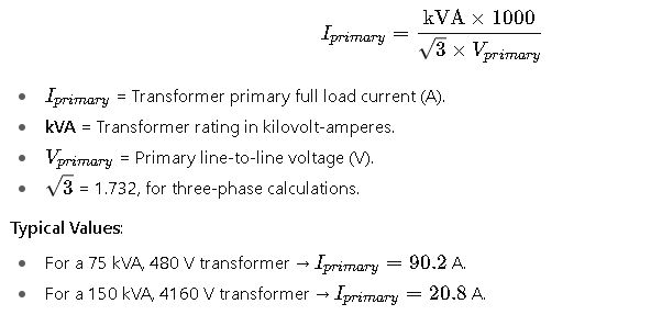
Formula 2: Transformer Full Load Current (Secondary)
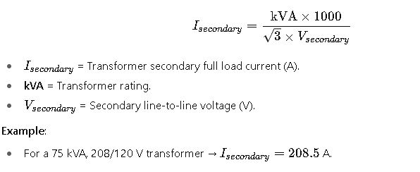
Formula 3: Maximum Primary OCPD (Per NEC 450.3(B))
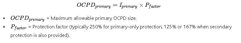
Formula 4: Maximum Secondary OCPD (Per NEC 450.3(B))
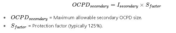
Formula 5: Next Standard Size Rule (NEC 240.4(B))
If calculated OCPD size does not correspond to a standard ampere rating from NEC 240.6(A), the next higher size may be used, provided it does not exceed the NEC maximum.
Example: 338 A calculated → Next standard OCPD is 350 A.
Real-World Application Examples of NEC Protection Sizing
Case Study 1: 75 kVA, 480 V to 208/120 V Transformer in a Commercial Building
A typical commercial building requires a step-down transformer to supply lighting and receptacle loads at 120 V while the main distribution operates at 480 V.
Step 1. Determine transformer ratings.
- Transformer size: 75 kVA.
- Primary voltage: 480 V (three-phase).
- Secondary voltage: 208/120 V (three-phase, wye).
Step 2. Calculate full-load currents.
- Primary FLA ≈ 90 A.
- Secondary FLA ≈ 208 A.
Step 3. Apply NEC primary protection rule.
- With secondary protection provided, NEC allows 125%–167% primary protection.
- Engineers often select 150 A or 175 A breaker on the primary side for coordination.
Step 4. Apply NEC secondary protection rule.
- Secondary OCPD must not exceed 125% of secondary FLA.
- 208 A × 1.25 = 260 A.
- Closest standard size: 300 A breaker on the secondary.
Step 5. Consider conductor protection.
- NEC 240.21(C) requires secondary conductors to be protected within 10 ft or 25 ft, depending on installation.
- Engineers ensure conductor ampacity ≥ OCPD rating.
Final design decision:
- 75 kVA transformer with 175 A primary breaker and 300 A secondary breaker, both complying with NEC limits.
- This setup ensures coordination, avoids nuisance tripping, and matches the building’s load profile.
Case Study 2: 500 kVA, 4160 V to 480 V Transformer in an Industrial Facility
An industrial plant installs a medium-voltage transformer to feed low-voltage switchgear.
Step 1. Transformer details.
- Rating: 500 kVA.
- Primary voltage: 4160 V.
- Secondary voltage: 480 V.
Step 2. Full-load currents.
- Primary FLA ≈ 70 A.
- Secondary FLA ≈ 601 A.
Step 3. Primary protection.
- NEC 450.3(A) applies (over 600 V).
- Protection is based on manufacturer recommendations, short-circuit duty, and relay coordination.
- Typically, a fused primary switch rated at 100 A or protective relays with current transformers (CTs) are used.
Step 4. Secondary protection.
- NEC requires secondary protection ≤125% of 601 A.
- 601 × 1.25 = 751 A → select an 800 A breaker.
Step 5. Additional considerations.
- Short-circuit withstand rating of secondary gear must exceed available fault current.
- Coordination study ensures downstream MCC breakers trip before transformer protection.
Final design decision:
- Primary: 100 A fused switch on 4160 V.
- Secondary: 800 A breaker on 480 V bus.
- Coordination verified with time-current curves.
Practical Engineering Considerations Beyond NEC
While NEC establishes maximum OCPD sizes, engineers consider many additional factors to ensure a safe and efficient design.
1. Selective Coordination
In systems with multiple levels of protection (utility → transformer → panel → branch circuits), coordination ensures that only the closest protective device to the fault opens.
- Example: If a branch circuit faults, the breaker in the panel should trip, not the transformer primary fuse.
- Achieved by time-current curve (TCC) analysis and selecting fuses/breakers with proper delay settings.
2. Short-Circuit Duty
Transformers contribute to fault currents.
- Large transformers (≥500 kVA) at low voltage can deliver tens of kA fault current.
- Secondary switchgear must have adequate interrupting rating (IR).
- NEC 110.9 and 110.10 require equipment withstand and clearing coordination.
3. Voltage Drop and Inrush Current
- Transformer inrush can be 8–12 times FLA for a few cycles.
- If the primary breaker is sized too close to FLA, nuisance tripping occurs.
- NEC’s allowance of 250% for primary-only protection addresses this issue.
4. Energy Efficiency and Derating
- Transformers near continuous loads (≥3 hours) must use 125% conductor sizing per NEC 215.2 and 210.19.
- Ambient temperature and altitude can require derating transformer capacity, indirectly affecting protection sizing.
5. Harmonics and Nonlinear Loads
Modern facilities often have VFDs, UPS systems, or LED lighting, generating harmonics.
- Harmonics increase transformer heating.
- Protection must sometimes be reduced (≤80% of NEC maximum) to protect against overheating.
- K-rated transformers or special OCPDs may be specified.
Extended Tables for Design Reference
Below is an expanded reference matrix engineers use for common transformer sizes in commercial and industrial systems.
Table 3. Practical Protection Ranges for Common Transformers (600 V and Below)
| kVA | Primary Voltage | Primary FLA (A) | Typical Primary OCPD Range (125%–250%) | Secondary Voltage | Secondary FLA (A) | Typical Secondary OCPD (125%) |
|---|---|---|---|---|---|---|
| 15 | 480 V | 18 | 30–45 A | 208/120 V | 41.7 | 60 A |
| 30 | 480 V | 36 | 50–90 A | 208/120 V | 83.4 | 110 A |
| 45 | 480 V | 54 | 70–135 A | 208/120 V | 125 | 175 A |
| 75 | 480 V | 90 | 125–225 A | 208/120 V | 208 | 300 A |
| 112.5 | 480 V | 135 | 175–338 A | 208/120 V | 313 | 400 A |
| 150 | 480 V | 181 | 225–451 A | 208/120 V | 417 | 600 A |
| 225 | 480 V | 271 | 350–677 A | 208/120 V | 626 | 800 A |
| 300 | 480 V | 361 | 450–902 A | 208/120 V | 834 | 1100 A |
| 500 | 480 V | 602 | 750–1504 A | 208/120 V | 1390 | 1750 A |
| 750 | 480 V | 903 | 1100–2256 A | 208/120 V | 2085 | 2600 A |