The relationship between kW, kVA, and PF is crucial, significantly impacting electrical engineering efficiency worldwide. Power factor influences system efficiency, equipment sizing, and energy costs, requiring accurate calculations for effective management.
KW → KVA & Power Factor Calculator
What is Power Factor?
Formulas Used
Three-phase: kVA = kW / PF
DC: kA = kW / V
What Are kW, kVA, and Power Factor?
Before analyzing the calculator, it is essential to clarify the terms involved:
- kW (kilowatts): Represents the real power consumed by a load, i.e., the actual useful work performed (lighting, heating, mechanical energy).
- kVA (kilovolt-amperes): Represents the apparent power, the vector sum of real power (kW) and reactive power (kVAR).
- Power Factor (PF): The ratio between real power and apparent power. It is dimensionless and varies between 0 and 1.

Where:
- PF = Power Factor (dimensionless)
- kW = Real Power in kilowatts
- kVA = Apparent Power in kilovolt-amperes
A PF = 1 indicates a purely resistive load (ideal scenario). Lower PF values indicate higher reactive power, leading to inefficiencies.
Extensive kW-kVA to Power Factor Tables
The following tables show commonly used values for converting between kW, kVA, and PF. These are reference points that engineers frequently encounter in electrical design and power quality analysis.
Table 1: Power Factor for Common kW-to-kVA Ratios
| kW (Real Power) | kVA (Apparent Power) | Power Factor (PF = kW/kVA) |
|---|---|---|
| 100 | 100 | 1.00 |
| 100 | 110 | 0.91 |
| 100 | 125 | 0.80 |
| 100 | 133 | 0.75 |
| 100 | 150 | 0.67 |
| 100 | 200 | 0.50 |
| 200 | 220 | 0.91 |
| 200 | 250 | 0.80 |
| 200 | 266 | 0.75 |
| 200 | 300 | 0.67 |
| 500 | 520 | 0.96 |
| 500 | 600 | 0.83 |
| 500 | 625 | 0.80 |
| 500 | 750 | 0.67 |
| 1000 | 1100 | 0.91 |
| 1000 | 1250 | 0.80 |
| 1000 | 1333 | 0.75 |
| 1000 | 1500 | 0.67 |
| 2000 | 2500 | 0.80 |
| 2000 | 3000 | 0.67 |
Table 2: Quick Reference – Power Factor Values
| Power Factor (PF) | kVA = kW / PF (Conversion Factor) |
|---|---|
| 1.00 | kVA = kW |
| 0.95 | kVA ≈ 1.05 × kW |
| 0.90 | kVA ≈ 1.11 × kW |
| 0.85 | kVA ≈ 1.18 × kW |
| 0.80 | kVA ≈ 1.25 × kW |
| 0.75 | kVA ≈ 1.33 × kW |
| 0.70 | kVA ≈ 1.43 × kW |
| 0.60 | kVA ≈ 1.67 × kW |
| 0.50 | kVA = 2.00 × kW |
These tables are fundamental tools for quickly estimating required kVA ratings for equipment or verifying system performance based on known kW and PF.
Formulas for kW-kVA to Power Factor Conversion
The core formula is:
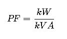
But in practical applications, engineers often work with multiple variables, such as voltage, current, and reactive power. The following are the main formulas:
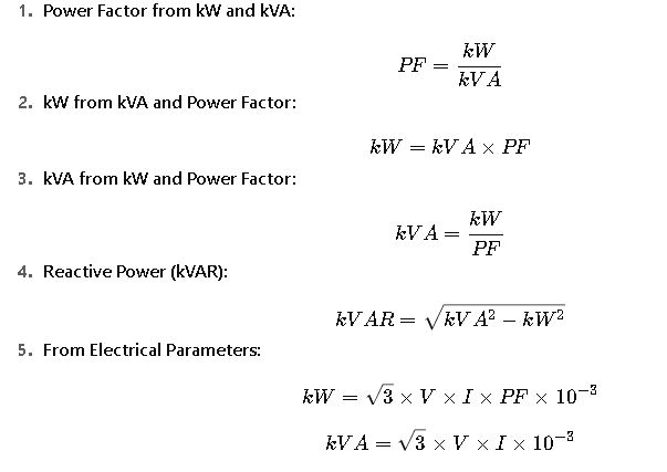
Where:
- V = Line voltage (Volts)
- I = Current (Amps)
- √3 = Factor for three-phase systems
These formulas provide a complete framework for converting between all relevant power quantities.
Detailed Explanation of Variables
- kW (kilowatts): Typically measured using power analyzers. In industrial systems, common ratings range from 10 kW (small motors) to several MW (large processes).
- kVA (kilovolt-amperes): Used to size generators, transformers, and UPS systems. Equipment is always rated in kVA, not kW, since power factor varies with load.
- Power Factor (PF): Typical values:
- 0.95–1.0: Efficient modern systems with correction capacitors.
- 0.80–0.90: Older industrial systems, lightly corrected.
- 0.60–0.75: Poorly corrected systems with inductive loads (large motors, welding).
- <0.60: Severe inefficiencies, usually non-compliant with utility standards.
Real-World Applications of kW-kVA to Power Factor Calculations
While the formulas and tables provide a theoretical framework, the practical importance of kW-kVA to power factor conversion becomes clear when analyzing real-world applications. Below are two detailed scenarios commonly faced in industrial and commercial power systems.
Case Study 1: Sizing a Backup Generator for an Industrial Plant
Scenario:
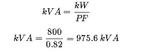
A manufacturing facility operates several induction motors for conveyor belts, compressors, and pumps. The total measured real power consumption (kW) is 800 kW. The facility has an average power factor of 0.82. The company needs to install a backup generator to cover the entire load in case of utility outages.
Step 1: Calculate Apparent Power (kVA)
The generator must be rated in kVA, not kW, since the power factor reduces the efficiency.
Step 2: Include a Safety Margin
Standards (such as IEEE Std 141 and IEC 60034) recommend a safety factor of 10–20% for transient loads.
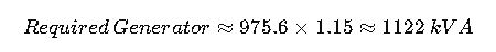
Step 3: Final Selection
The facility should select a generator with a minimum rating of 1125 kVA.
Insight:
If the facility improved its PF from 0.82 to 0.95 using capacitor banks, the required generator size would decrease significantly:

By correcting power factor, the company could reduce generator size from 1125 kVA to 1000 kVA, leading to significant cost savings on purchase and operating efficiency.
Case Study 2: Utility Power Factor Penalty on a Commercial Building
Scenario:
A commercial building consumes 500 kW during peak operation. The local utility requires customers to maintain a minimum PF of 0.90; otherwise, penalties are applied. The measured PF is 0.75.

Step 4: Business Impact
- Without correction, the utility charges penalties because of excess reactive demand.
- By installing a 203 kVAR capacitor bank, the building improves PF to 0.90, avoiding penalties and reducing transformer loading.
Result: The investment in power factor correction pays back within months through reduced utility bills.
Why Power Factor Matters in kW-kVA Calculations
The two cases demonstrate that poor PF leads to:
- Oversized (and more expensive) generators, transformers, and UPS systems.
- Higher current flow, which increases copper losses (I²R) and heating in conductors.
- Utility penalties for excessive reactive power demand.
- Reduced overall energy efficiency.
On the other hand, improving PF brings:
- Optimized equipment sizing.
- Lower operational costs.
- Compliance with utility standards (often 0.90–0.95 minimum).
- Extended equipment lifespan due to reduced thermal stress.
Regulatory Standards and Industry Guidelines
Understanding kW, kVA, and PF also requires knowledge of regulatory and engineering standards that govern power quality worldwide.
IEEE Standards
- IEEE 141 (Red Book): Provides recommendations for electrical power distribution in industrial plants, including PF correction methods.
- IEEE 1459: Defines power components (active, reactive, apparent) for accura te measurements.
- IEEE 519: Establishes limits for harmonic distortion, which indirectly affects power factor.
IEC Standards
- IEC 60034-1: Governs rotating electrical machines, including efficiency and PF requirements.
- IEC 61000: Addresses electromagnetic compatibility and power quality, including PF correction.
Utility Regulations
- Many utilities impose PF penalties below 0.90 or 0.95.
- Some regions incentivize customers who maintain PF above a certain threshold, reducing apparent demand charges.
Frequently Asked Questions (SEO-Optimized)
1. What is the difference between kW and kVA?
- kW is real power, performing useful work.
- kVA is apparent power, including both real and reactive components.
2. How do you calculate power factor from kW and kVA?
Use the formula:
3. Why do generators and transformers use kVA, not kW?
Because kW depends on load PF, which varies. kVA is fixed and ensures safe equipment sizing.
4. What is a good power factor value?
- Above 0.95: Excellent
- 0.90–0.95: Acceptable
- 0.80–0.90: Needs correction
- Below 0.80: Inefficient and usually penalized
5. How can power factor be improved?
- Installing capacitor banks
- Using synchronous condensers
- Applying active harmonic filters
Authoritative References
For further reading and validation: