Overload relays protect motors and equipment from thermal damage caused by prolonged overcurrent conditions. IEC 60255 defines standards, formulas, and performance requirements, enabling accurate calculations and real-world applications.
Overload Relay Calculator – IEC
How is the overload relay current calculated?
Why include motor efficiency and power factor?
Common Overload Relay Settings Table
To facilitate the understanding of overload relay settings, the following table presents typical settings based on motor rated currents and service factors:
| Motor Rated Current (A) | Service Factor (SF) | Overload Relay Setting (A) | Application Example |
|---|---|---|---|
| 5 | 1.0 | 5.0 | Small pumps, fans |
| 10 | 1.15 | 11.5 | Conveyor belts, compressors |
| 20 | 1.0 | 20.0 | Industrial mixers, blowers |
| 30 | 1.15 | 34.5 | Large pumps, crushers |
| 50 | 1.0 | 50.0 | Heavy-duty motors, mills |
| 75 | 1.15 | 86.25 | Industrial presses, crushers |
| 100 | 1.0 | 100.0 | Large compressors, pumps |
Note: These settings are based on IEC 60255 standards and should be adjusted according to specific motor characteristics and application requirements.
Formulas for Overload Relay Calculations
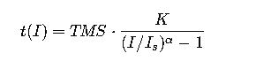
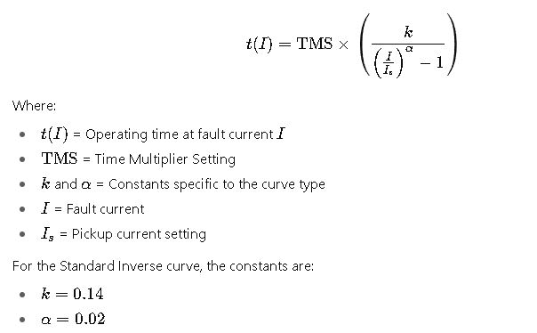
IEC 60255 Standard Inverse Curve
The IEC 60255 standard inverse curve is defined by the formula:
IEEE C37.112 Moderately Inverse Curve
The IEEE C37.112 moderately inverse curve is given by:
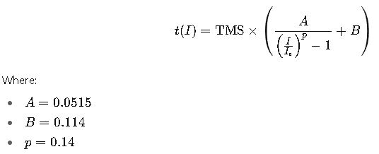
Note: The constants AAA, BBB, and ppp vary for different curves as per IEEE standards.
Real-World Application Examples
Example 1: Motor Protection in a Conveyor System
Scenario: A conveyor system utilizes a 20 A motor with a service factor of 1.15. The motor operates in an environment where the ambient temperature is 40°C.
Calculation:
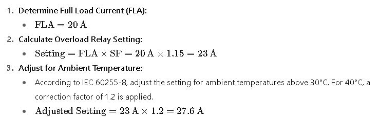
Conclusion: The overload relay should be set to 27.6 A to protect the motor under the specified conditions.
Example 2: Protection of a Large Pump Motor
Scenario: A 75 A motor with a service factor of 1.0 drives a large pump. The motor starts with a starting current of 6 times the rated current.
Calculation:
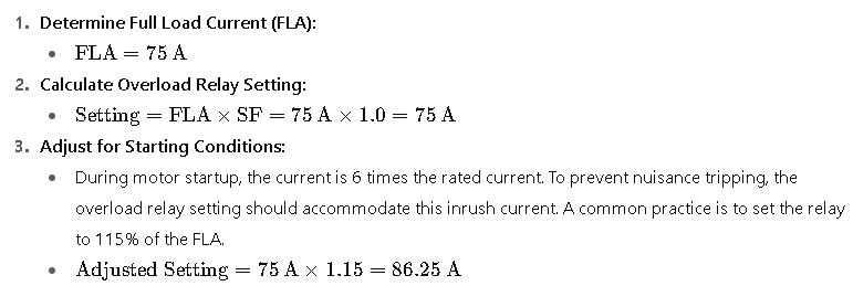
Conclusion: The overload relay should be set to 86.25 A to ensure protection without unnecessary tripping during startup.
Additional Considerations
- Ambient Temperature Compensation: Overload relay settings should be adjusted for ambient temper atures above 30°C to account for the reduced cooling effect on the motor.
- Motor Starting Characteristics: For motors with high inrush currents, such as those started across the line, the overload relay settings should be adjusted to prevent tripping during startup.
- Relay Characteristics: Different types of overload relays (e.g., thermal, electronic) have varying characteristics and response times. The selection should align with the motor’s protection requirements.
- Coordination with Other Protection Devices: Overload relays should be coordinated with other protection devices in the system, such as short-circuit protection, to ensure selective tripping and minimize system downtime.
Conclusion
Accurate overload relay settings are crucial for protecting motors and ensuring the reliability of electrical systems. By adhering to IEC 60255 standards and considering factors such as motor characteristics, ambient temperature, and startup conditions, engineers can design effective protection schemes that prevent damage and optimize performance.
Frequently Asked Questions (FAQ) – Overload Relay Calculator (IEC)
1. What is an overload relay?
An overload relay is a protection device that safeguards electric motors from overheating caused by prolonged overcurrent. It detects excess current and trips the motor circuit before thermal damage occurs.
2. How does an IEC overload relay work?
IEC overload relays operate based on thermal or electronic principles. Thermal relays use bimetallic strips to sense heat, while electronic relays monitor current electronically and provide adjustable trip characteristics according to IEC 60255 standards.
3. What are the common types of overload relays?
- Thermal Overload Relays: Rely on heating elements and bimetallic strips.
- Electronic Overload Relays: Offer precise trip settings, adjustable curves, and built-in diagnostics.
- Solid-State Relays: High-accuracy electronic relays with programmable inverse-time curves.
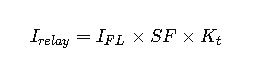
4. How do I calculate the relay setting for a motor?
The overload relay setting depends on:
- Motor full-load current (FLA)
- Motor service factor (SF)
- Ambient temperature adjustment
- Startup current factors
Formula:
5. What are IEC standard inverse curves?
IEC defines inverse-time tripping curves:
- Standard Inverse – suitable for normal industrial motors
- Very Inverse – for high-inertia loads
- Extremely Inverse – for long-running motors or pumps
Trip time is calculated using: