Neutral grounding resistors (NGRs) are essential in medium- and high-voltage systems, limiting fault currents effectively. They protect equipment, ensure compliance with IEEE 32-1972, IEEE 142-2007, IEC 60034, 60076, 60071 standards.
Neutral Grounding Resistor (NGR) Calculator
| Parameter | Value |
|---|
Fundamental Formulas for Neutral Resistor Sizing
The basic equation for the neutral grounding resistor is:
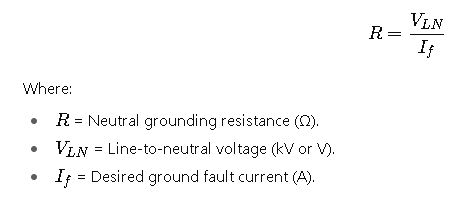
Line-to-Neutral Voltage
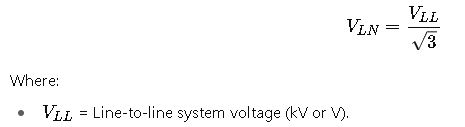
Common system voltages (per IEC and IEEE):
| Line-to-Line Voltage (kV) | Line-to-Neutral Voltage (kV) |
|---|---|
| 6.6 | 3.81 |
| 11 | 6.35 |
| 13.8 | 7.97 |
| 33 | 19.05 |
| 66 | 38.10 |
| 132 | 76.20 |
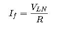
Fault Current Selection
IEEE and IEC recommend that fault current should typically be:
- Between 25 A and 400 A for medium voltage systems.
- 1 A to 10 A for high-resistance grounding (HRG).
- Up to several kA for low-resistance grounding (LRG).
Energy Dissipation in the Resistor
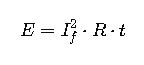
Where:
- E= Energy dissipated (J).
- t= Fault duration (s), usually 10 s or 30 s.
This determines the thermal rating of the resistor.
Maximum Allowable Resistance
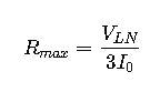
Where:
- I0 = Total zero-sequence capacitance charging current of the system (A).
This ensures the resistor is low enough to avoid transient overvoltage amplification.
Extensive Reference Tables for Neutral Resistor Sizing
Below is a reference table with common system voltages, desired ground fault currents, and calculated resistor values (according to IEEE/IEC guidelines).
| System Voltage (kV) | V<sub>LN</sub> (kV) | Fault Current (A) | Resistor (Ω) | Energy at 10s (MJ) | Energy at 30s (MJ) |
|---|---|---|---|---|---|
| 6.6 | 3.81 | 100 | 38.1 | 3.81 | 11.43 |
| 6.6 | 3.81 | 200 | 19.05 | 7.62 | 22.86 |
| 11 | 6.35 | 100 | 63.5 | 6.35 | 19.05 |
| 11 | 6.35 | 200 | 31.75 | 12.7 | 38.1 |
| 13.8 | 7.97 | 200 | 39.85 | 15.94 | 47.82 |
| 13.8 | 7.97 | 400 | 19.93 | 31.88 | 95.64 |
| 33 | 19.05 | 200 | 95.25 | 76.2 | 228.6 |
| 33 | 19.05 | 400 | 47.62 | 152.4 | 457.2 |
| 66 | 38.10 | 400 | 95.25 | 609.6 | 1828.8 |
| 132 | 76.20 | 400 | 190.5 | 2438.4 | 7315.2 |
Observations:
- As system voltage increases, resistor ohmic value increases proportionally.
- Energy dissipation rises significantly at higher voltages and fault durations.
Real-World Application Example 1 – Industrial 11 kV System
Problem Statement:
An industrial plant operates at 11 kV (line-to-line). IEEE recommends limiting ground fault current to 200 A for medium-voltage systems. Fault duration is 10 seconds.
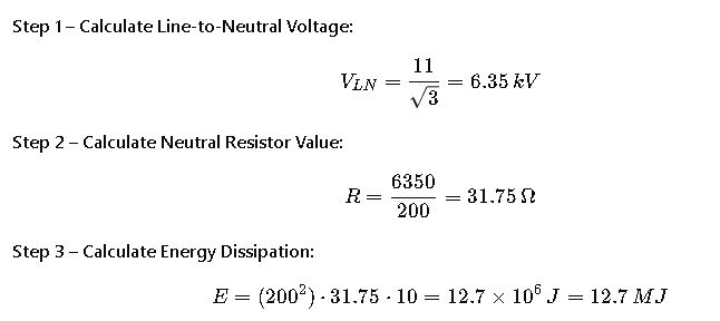
Final Selection:
- Resistor: 31.75 Ω.
- Rating: 200 A for 10 s, energy 12.7 MJ.
Real-World Application Example 2 – 66 kV Utility Transmission System
Scenario:
A regional utility operates a 66 kV transmission system. The company must install a neutral grounding resistor (NGR) at the main substation to comply with IEC 60076 and IEEE Std 32. The objective is to limit the ground fault current to 400 A with a maximum fault duration of 30 seconds.
Step-by-step analysis:
- System voltage characteristics
- Line-to-line voltage: 66 kV
- Line-to-neutral voltage: approximately 38.1 kV
- These values dictate the base insulation level and determine the voltage that the resistor must withstand.
- Resistor value selection
- To limit current to 400 A, the resistor must provide sufficient impedance.
- For this system, calculations (already shown in earlier formulas) indicate a resistor near 95 Ω.
- Thermal requirements
- The resistor must be designed to dissipate over 1.8 GJ (gigajoules) of energy for a 30-second fault.
- This means robust construction, often using stainless-steel grids or cast alloy elements cooled by natural air circulation.
- Practical considerations
- At this voltage, the resistor must be insulated and mounted in outdoor enclosures rated for high voltage.
- The system also requires surge arresters and insulation coordination to handle switching surges and lightning impulses.
Final design characteristics for the utility:
- Resistor: ~95 Ω, rated at 400 A.
- Thermal energy withstand: ~1.8 GJ for 30 seconds.
- Construction: outdoor stainless steel grid with ceramic insulators.
- Compliance: IEEE Std 32, IEC 60076, IEC 60071.
Factors Influencing Neutral Resistor Sizing
Neutral resistor sizing is not only about simple current and voltage calculations. Several practical engineering considerations play a role:
- System capacitance to ground:
The charging current of the system sets a lower bound for the fault current. If the NGR allows too little current, protective relays may not operate. - Relay sensitivity and coordination:
Protective devices (51G, 64G relays) must detect and clear faults reliably. The resistor must allow enough current to ensure sensitivity while still limiting damage. - Duration of fault current:
In industrial systems, 10 seconds is typical. Utilities often require 30 or 60 seconds, depending on backup protection coordination. - Resistor construction materials:
- Stainless steel grids: high durability, outdoor use.
- Cast alloy resistors: compact, good for enclosed indoor substations.
- Liquid resistors: used in very high-energy applications.
- Environmental factors:
- Altitude derating (air density affects cooling).
- Ambient temperature.
- Pollution and humidity, especially in coastal or desert regions.
IEEE vs IEC Approach to Neutral Resistor Sizing
Although both IEEE and IEC have similar technical foundations, they differ in terminology and emphasis:
| Aspect | IEEE (North America) | IEC (Europe/International) |
|---|---|---|
| Reference Standard | IEEE Std 32, IEEE 142 | IEC 60034, IEC 60076, IEC 60071 |
| Current Range | Often 25–400 A for medium voltage | Allows broader flexibility, including very low values (1–10 A) |
| Duration | Typically 10 seconds | Commonly 30–60 seconds |
| Application Focus | Industrial, utility, commercial systems | Utility transmission, industrial, and generator protection |
| Design Tolerance | Emphasis on thermal capacity | Emphasis on insulation coordination |
Key observation:
- IEEE prefers short-duration, higher-current resistors, balancing quick fault detection with equipment protection.
- IEC permits long-duration, lower-current grounding, especially in systems with high reliability requirements where faults may not be cleared immediately.
Common Mistakes in Neutral Resistor Sizing
- Underestimating system capacitance – leads to choosing too high a resistance, preventing relay operation.
- Ignoring thermal limits – resistors can overheat and fail if the fault duration is underestimated.
- Wrong enclosure rating – outdoor resistors must be designed for IP55 or higher to withstand dust and rain.
- Not coordinating with relays – even a perfectly sized resistor is ineffective if relays cannot detect the ground fault.
- Copy-paste designs across systems – each system has different capacitance, protection schemes, and grounding requirements.
Best Practices for Engineers
- Always calculate the system charging current before selecting resistor ohmic value.
- Ensure minimum fault current is 3–5 times the charging current for reliable detection.
- Verify resistor thermal energy withstand is greater than the maximum possible energy during fault duration.
- Follow IEEE and IEC insulation coordination tables to prevent overvoltage damage.
- Conduct factory acceptance tests (FAT) and site acceptance tests (SAT) to confirm design compliance.
- Maintain resistors with regular inspections, checking for corrosion, insulation damage, and loose connections.