Motor Inrush Current Calculator (IEC) helps determine peak starting currents in electric motors for protection design.
This tool ensures proper breaker selection, cable sizing, and coordination according to IEC standards and practices.
Motor Inrush Current Calculator (IEC)
Typical Multipliers
| Method | Factor × IFL |
|---|---|
| DOL | 6 – 8 |
| Star‑Delta | 2 – 3 |
| Soft‑Starter | 1.8 – 3 |
| VFD | 1.0 – 1.2 |
FAQs
What is “locked‑rotor” current?
The peak current drawn when power is applied but the rotor is not yet turning. Often 2–10× the rated full‑load current (IFL).
Do I need to oversize breakers or generators?
Yes. Protective devices and gensets must ride through the surge without nuisance tripping or excessive voltage drop (keep it ≤10 %).
Best starting method for pumps, fans or compressors?
Star‑Delta or a soft‑starter reduces inrush to ~2–3× IFL. A VFD gives the lowest surge (~1.1×) and speed control. Use DOL only if the supply can handle 6–8×.
Extensive Table of Typical Inrush Current Multipliers (IEC Reference)
The inrush current of motors varies depending on motor size, type, starting method, and application. IEC 60034-12 provides general guidance, and industry practice supplements this with empirical data.
| Motor Power (kW) | Voltage (V) | Starting Method | Inrush Current Multiplier (×FLC) | Typical Inrush Current Duration (s) |
|---|---|---|---|---|
| 0.75 | 400 | Direct-On-Line (DOL) | 6.5 | 0.4 – 0.8 |
| 1.5 | 400 | DOL | 6.5 | 0.6 – 1.0 |
| 7.5 | 400 | DOL | 7.0 | 0.8 – 1.5 |
| 15 | 400 | DOL | 7.5 | 1.2 – 2.0 |
| 30 | 400 | Star-Delta | 2.5 | 1.5 – 3.0 |
| 55 | 400 | Star-Delta | 2.3 | 2.0 – 3.5 |
| 75 | 400 | Soft Starter | 1.8 – 3.0 | Configurable |
| 110 | 400 | Variable Frequency Drive (VFD) | 1.0 – 1.2 | Controlled |
| 160 | 400 | DOL (special case) | 8.0 | 2.5 – 5.0 |
Notes:
- Values are generalized for IEC-standard three-phase squirrel cage induction motors.
- Starting duration depends on motor inertia and load torque.
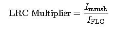
- Inrush multiplier (also called Locked Rotor Current, or LRC) is defined as:
IEC-Based Formulas for Inrush Current Calculation
1. Full Load Current (FLC) – Base for Inrush
For three-phase motors:
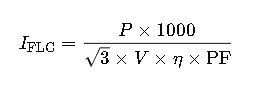
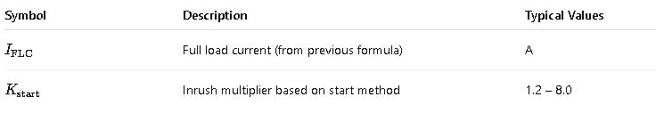
Where:
| Symbol | Description | Typical Range/Unit |
|---|---|---|
| P | Rated motor power | kW |
| V | Line voltage | V |
| η (eta) | Efficiency | 0.85 – 0.95 |
| PF | Power factor | 0.80 – 0.95 |
| √3 | Three-phase constant (≈1.732) | Dimensionless |
2. Inrush Current (Iinrush) – Main Formula

Where:

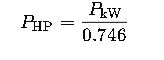
3. Alternative Formula Using Motor Nameplate Locked Rotor Code (NEMA)
Though this guide focuses on IEC, many motors still use NEMA Locked Rotor Code Letters (A–V). For IEC, equivalent current is approximated by:
Convert power to HP using:
Typical Starting Current Multipliers by Method (IEC Guidance)
| Starting Method | Inrush Multiplier | Notes |
|---|---|---|
| Direct-On-Line (DOL) | 6.0 – 8.0×FLC | High torque and high current |
| Star-Delta | 2.0 – 3.5×FLC | 33% torque, 33% voltage at start |
| Autotransformer (50%) | 1.6 – 3.5×FLC | Depends on tap setting (50%, 65%, 80%) |
| Soft Starter (torque ramp) | 1.5 – 3.0×FLC | Adjustable slope, minimizes mechanical stress |
| VFD | 1.0 – 1.2×FLC | Smoothest, most efficient startup |
Real-World Example 1: 15 kW Motor, DOL Start
Given:
- Power: 15 kW
- Voltage: 400 V
- Efficiency (η): 0.92
- Power Factor: 0.88
- Start Method: DOL
- Inrush Multiplier: 7.5
Step 1 – Calculate FLC
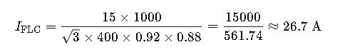
Step 2 – Calculate Inrush Current
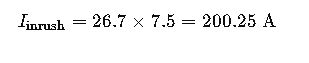
Result:
The motor will draw approximately 200 A during startup. Circuit breakers and cables must be rated accordingly.
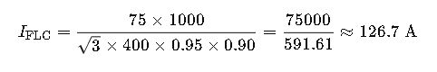
Real-World Example 2: 75 kW Motor, Star-Delta Start
Given:
- Power: 75 kW
- Voltage: 400 V
- Efficiency (η): 0.95
- Power Factor: 0.90
- Start Method: Star-Delta
- Inrush Multiplier: 2.8
Step 1 – Calculate FLC
Step 2 – Calculate Inrush Current
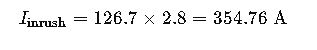
Result:
In this star-delta configuration, the motor’s inrush current is 355 A, significantly less than DOL and within the acceptable trip settings for many IEC-based MCCBs or protection relays.
Impact of Inrush Current on Motor Protection Selection
1. Thermal Overload Relays (IEC 60947-4-1)
Thermal relays are designed to mimic the heating effect of current on motor windings. However, inrush current can cause them to trip if:
- The relay is incorrectly set too close to FLC.
- There’s no intentional time delay to ignore startup surges.
Solution:
Use Class 10, 20, or 30 relays depending on start duration. For motors with long acceleration time (e.g., conveyors), Class 20 or 30 should be used.
| Relay Class | Trip Time at 7.2×FLC (Cold) | Suitable Applications |
|---|---|---|
| Class 10 | ≤10 s | Pumps, fans (short start) |
| Class 20 | ≤20 s | General industrial loads |
| Class 30 | ≤30 s | High inertia loads |
2. Magnetic Circuit Breakers and MCCBs
Inrush current affects the magnetic (instantaneous) setting. To avoid nuisance trips:
- IEC 60947 recommends adjustable magnetic trip units in MCCBs.
- Set the magnetic trip at 10–12× FLC for DOL starts, 4–6× FLC for star-delta or soft starts.
Comparative Table: Starting Methods vs. Inrush & Protection Settings
| Start Method | Inrush Multiplier | Recommended Protection Trip Setting | Notes |
|---|---|---|---|
| DOL | 6 – 8×FLC | Magnetic: 10 – 12×FLC | High torque; shortest start time |
| Star-Delta | 2 – 3.5×FLC | Magnetic: 4 – 6×FLC | Lower torque; longer start time |
| Soft Starter | 1.5 – 3.0×FLC | Thermal: Class 20 or 30 | Adjustable ramp time, less stress |
| VFD | ~1.1×FLC | May not need dedicated starter | Inrush is almost eliminated |
Effects of Inrush Current on System Design
1. Cable Sizing
IEC 60287 and 60364 require cables to carry the inrush current without:
- Exceeding temperature rise limits (especially PVC insulation)
- Triggering upstream protection prematurely
Use a de-rating factor or short-time thermal withstand method.
2. Transformer Sizing
For large motor starts, transformers must not drop below 85% voltage during inrush. Use:

If voltage drop > 15%, consider:
- Adding soft starters
- Oversizing transformer
- Using VFDs
Frequently Asked Questions (FAQs)
What is the IEC standard for motor starting current?
IEC 60034-12 provides guidance on starting performance, including locked-rotor current (inrush), torque, and acceleration time.
How long does inrush current last in a motor?
Inrush typically lasts from 0.2 to 5 seconds, depending on load, start method, and motor inertia. High-inertia systems (e.g., crushers) may require longer acceleration.
How can I reduce motor inrush current?
- Use soft starters
- Use star-delta starters
- Implement VFDs
- Ensure proper load torque matching
- Can inrush current damage the motor?
Not directly — motors are designed to handle inrush — but it can overstress the supply system, cause voltage sags, and nuisance trip protection devices if not properly accounted for.
Summary Table: IEC Inrush Values for Fast Reference
| Motor kW | Voltage (V) | Start Method | FLC (A) | Inrush Multiplier | Inrush Current (A) |
|---|---|---|---|---|---|
| 0.75 | 400 | DOL | 1.95 | 6.5 | 12.7 |
| 5.5 | 400 | DOL | 10.5 | 7.0 | 73.5 |
| 15 | 400 | Star-Delta | 26.7 | 2.8 | 74.8 |
| 55 | 400 | Soft Starter | 98.6 | 2.5 | 246.5 |
| 110 | 400 | VFD | 196.2 | 1.1 | 215.8 |
Advanced Engineering Considerations for Motor Inrush (IEC Context)
Harmonics and Power Quality during Inrush
Although the inrush current is transient, its steep rise can introduce voltage dips, transient harmonics, and flicker into the power system. IEC 61000-3-3 addresses voltage fluctuations and flicker in public low-voltage systems. This is critical for:
- Industrial parks with multiple motors
- Grid-connected systems sensitive to disturbances
- Systems requiring high power quality (e.g., data centers)
Mitigation Techniques:
- Sequential motor starting (time delay between motors)
- Dedicated motor feeders
- Soft starters with controlled ramp-up
- Power quality analyzers to validate IEC 61000 compliance
Coordination with Backup Power Systems (Generators)
Generators have limited short-circuit capacity compared to utility power. A motor starting DOL may cause:
- Severe voltage sag
- Generator instability
- Reverse power protection tripping
Key Design Tip:
For generator-fed systems, avoid DOL starts above 25% of generator kVA rating. Use soft starters or VFDs. Always simulate motor-starting transients with power system analysis tools like ETAP, DIgSILENT, or SKM.
IEC vs. NEMA Approach: What You Should Know
| Characteristic | IEC | NEMA |
|---|---|---|
| Inrush Current | Expressed as multiplier of FLC | Based on Locked Rotor Code (kVA/HP) |
| Standards | IEC 60034-12 | NEMA MG-1 |
| Region | Europe, Asia, Africa, others | North and Central America |
| Protection Coordination | IEC 60947-4, -2 | UL489, ANSI C37 |
| Motor Classes | IE1, IE2, IE3, IE4 (efficiency) | Design A, B, C, D |
Tip: Even in IEC environments, some OEMs use NEMA motor datasheets. Convert accordingly.
Checklist for Inrush Current Calculation and Protection (IEC)
✔️ Identify motor power (kW), voltage, PF, and efficiency
✔️ Select starting method (DOL, Star-Delta, VFD, etc.)
✔️ Calculate Full Load Current using IEC formula
✔️ Apply correct inrush multiplier per method
✔️ Choose correct thermal/magnetic protection settings
✔️ Validate system components (cable, breaker, transformer)
✔️ Check IEC protection class for coordination (60947)
✔️ Validate flicker/harmonics compliance (IEC 61000)
Application Fields Where Inrush Current Calculation is Critical
- Industrial Automation: Conveyor belts, crushers, air compressors
- Infrastructure: Water pumps, HVAC motors, escalators
- Marine & Offshore: Fire pumps, thrusters (soft start preferred)
- Aviation Ground Systems: Baggage systems and runway systems
- Healthcare Facilities: Ventilation motors and critical backup loads
Final Thoughts: Why This Matters in Real-World Engineering
Motor inrush current is not just an academic calculation—it’s a practical constraint in every project involving motors. A 250 A inrush current that lasts just one second can trip a poorly selected breaker, overload a transformer, or destabilize a generator. That’s why engineers must calculate, anticipate, and design with precision.
This Motor Inrush Current Calculator (IEC) framework gives you the necessary tools to:
- Avoid costly over-dimensioning
- Improve energy efficiency
- Extend equipment life
- Ensure system stability
- Guarantee safety under IEC guidelines