The Motor Full Load Current Calculator, based on NEC and IEEE standards, ensures accurate electrical system design. It provides standardized reference values for conductor sizing, overload protection, breaker selection, and motor installation reliability.
Motor Full‑Load Current Calculator — NEC & IEEE
Convert motor power (HP or kW) into estimated line current (A). Includes single‑phase, three‑phase and DC options. Use nameplate or NEC tables for exact FLC.
Extended NEC Full Load Current Tables
The NEC provides standard tables (primarily Table 430.247, 430.248, 430.249, and 430.250) listing typical motor full load currents based on horsepower, phase, and voltage. These values are not necessarily equal to the actual nameplate current but are instead standardized values used for sizing equipment.
Below is a consolidated table of common NEC motor full load currents for three-phase and single-phase motors (60 Hz, standard efficiency).
NEC Table — Three-Phase Induction Motors (Selected Values)
| Horsepower (HP) | 200V (A) | 230V (A) | 460V (A) | 575V (A) |
|---|---|---|---|---|
| 1 | 4.6 | 4.2 | 2.1 | 1.7 |
| 3 | 13.6 | 12 | 6.0 | 4.8 |
| 5 | 21.7 | 20 | 10.0 | 8.0 |
| 7.5 | 32.2 | 28 | 14.0 | 11.3 |
| 10 | 40.2 | 36 | 18.0 | 14.4 |
| 15 | 58.0 | 52 | 26.0 | 20.8 |
| 20 | 74.8 | 65 | 32.0 | 25.6 |
| 25 | 92.0 | 80 | 40.0 | 32.0 |
| 30 | 110 | 96 | 48.0 | 38.4 |
| 40 | 146 | 124 | 62.0 | 49.6 |
| 50 | 180 | 156 | 78.0 | 62.4 |
| 75 | 265 | 231 | 117 | 93.6 |
| 100 | 361 | 312 | 156 | 124 |
| 200 | 667 | 590 | 295 | 236 |
| 300 | 967 | 853 | 427 | 342 |
| 400 | 1242 | 1092 | 546 | 437 |
| 500 | 1550 | 1360 | 680 | 544 |
NEC Table — Single-Phase Motors (Selected Values)
| Horsepower (HP) | 115V (A) | 230V (A) |
|---|---|---|
| 0.25 | 4.4 | 2.2 |
| 0.5 | 9.0 | 4.5 |
| 1.0 | 16.0 | 8.0 |
| 2.0 | 24.0 | 12.0 |
| 3.0 | 34.0 | 17.0 |
| 5.0 | 56.0 | 28.0 |
| 7.5 | 80.0 | 40.0 |
| 10 | 100.0 | 50.0 |
IEEE Standardized Current Reference
IEEE provides slightly different guidance, especially when high-efficiency (NEMA Premium®) or synchronous motors are considered. IEEE Std. 112 and IEEE Red Book (Std. 141) give correction factors for motors operating at different efficiencies, power factors, and duty cycles.
For example, a 100 HP, 460V, three-phase induction motor may show:
- NEC FLC (Table 430.250): 156 A
- IEEE Typical Nameplate (High Efficiency): 148–152 A
This discrepancy demonstrates why NEC tables are used strictly for sizing and not for load studies or protective device setting.
Formulas for Motor Full Load Current Calculation
Although the NEC prescribes tabulated FLC values for equipment sizing, engineers often calculate approximate currents for analysis. The general equations are:
1. Three-Phase Motors
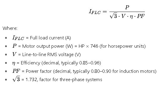
Common values:
- Efficiency: 90–95% for large motors, 82–88% for small ones
- PF: 0.85 typical for design B induction motors
2. Single-Phase Motors
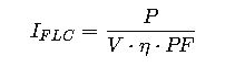
Variables are the same as above, but without the √3 factor since single-phase systems only involve one voltage path.
3. Relationship Between NEC Tables and Calculated Values
The NEC uses slightly inflated FLC values for conservative sizing. For instance, if a 10 HP, 460V, three-phase motor is analyzed:
- Calculation (η=0.9, PF=0.85):
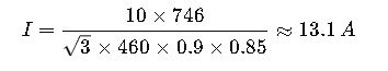
- NEC Table 430.250 value:
14.0 A
Thus, the NEC’s table value is deliberately conservative.
Variable Explanations and Common Ranges
- Horsepower (HP): Rated mechanical output, most common values range from fractional HP to thousands of HP.
- Voltage (V): Standard motor voltages include 115V, 208V, 230V, 460V, and 575V in North America; 400V and 690V in IEC regions.
- Efficiency (η): Fraction of input power converted to shaft power. Small motors: 80–88%. Large motors: 92–96%.
- Power Factor (PF): Ratio of real power to apparent power. Common range: 0.80–0.92 at full load. Lower at part load.
- Service Factor (SF): Optional rating allowing short-term overloading (typically 1.15). Does not affect FLC calculation but impacts thermal performance.
Practical Application of Motor Full Load Current in Engineering Design
Understanding the standardized FLC values is not just an academic exercise. Engineers, electricians, and designers use these values daily to ensure safety, reliability, and compliance with NEC and IEEE standards. Below are two detailed real-world cases that illustrate the importance of using FLC correctly.
Case Study 1 — Industrial Pump Installation (Three-Phase, 100 HP Motor at 460V)
Scenario:
A water treatment facility installs a 100 HP, 460V, three-phase induction motor to drive a centrifugal pump. The design engineer must size the conductors, protective devices, and feeder.
Step 1 – Reference NEC Table 430.250
From NEC Table 430.250, the FLC for a 100 HP, 460V motor is 156 A.
Step 2 – Conductor Sizing
- NEC 430.22 requires conductors to be sized at 125% of motor FLC.
- Conductor ampacity = 156 A × 1.25 = 195 A minimum.
- Using NEC Table 310.16, a 3/0 AWG copper conductor (200 A rated at 75°C) is selected.
Step 3 – Overload Protection
- NEC 430.32 requires overload protection based on 125% of motor nameplate current.
- Assuming a nameplate current of 150 A (slightly lower than NEC table), overloads are set at 150 × 1.25 = 188 A.
Step 4 – Short-Circuit and Ground-Fault Protection
- NEC 430.52 allows the use of an inverse time circuit breaker sized up to 250% of motor FLC.
- Maximum breaker size = 156 × 2.5 = 390 A.
- The engineer selects a 350 A breaker, balancing protection and selectivity.
Step 5 – Verification
- Motor starter rating is checked against NEMA sizes.
- For 100 HP at 460V, NEMA Size 5 starter is selected.
Result:
The installation complies with NEC, ensures reliability, and protects against overload and short circuits.
Case Study 2 — Commercial HVAC System (Single-Phase, 10 HP Motor at 230V)
Scenario:
A large office building installs a 10 HP, 230V, single-phase motor for an HVAC compressor. The electrical designer must size the feeder and protective devices.
Step 1 – Reference NEC Table 430.248
For 10 HP, 230V single-phase, the NEC table gives an FLC of 50 A.
Step 2 – Conductor Sizing
- NEC 430.22 → 125% of FLC = 50 × 1.25 = 62.5 A.
- From NEC Table 310.16, 4 AWG copper conductor (70 A rated at 75°C) is selected.
Step 3 – Overload Protection
- Overloads are based on 125% of nameplate current.
- Assuming a nameplate of 48 A, overloads set at 60 A.
Step 4 – Short-Circuit Protection
- NEC 430.52 → Inverse time breaker up to 250% of FLC.
- Maximum breaker size = 50 × 2.5 = 125 A.
- Selected breaker = 100 A.
Step 5 – Additional Considerations
- HVAC compressors often experience high inrush currents.
- Time-delay fuses could also be used, rated at 175% of FLC = 87.5 A, rounded to 90 A fuse.
Result:
The HVAC motor is safely installed, with adequate protection against overload and inrush conditions.
Extended Global Coverage — IEC Equivalent FLC Values
For international projects, engineers must also be aware of IEC 60034 standards, which define efficiency classes (IE1 to IE4) and provide current references at different voltages and frequencies.
IEC Typical Three-Phase Motor Currents (400V, 50 Hz)
| Power (kW) | FLC (A) | Efficiency Class (IE3) |
|---|---|---|
| 0.75 | 1.8 | 82% |
| 1.5 | 3.2 | 84% |
| 3.0 | 5.8 | 86% |
| 5.5 | 10.5 | 88% |
| 11.0 | 20.0 | 90% |
| 22.0 | 40.0 | 92% |
| 55.0 | 97.0 | 94% |
| 110.0 | 192.0 | 95% |
| 250.0 | 435.0 | 96% |
Key observation: IEC values align closely with IEEE-calculated currents but are generally lower than NEC tables, since NEC intentionally inflates FLC for equipment sizing safety.
Engineering Considerations Beyond NEC
When using motor FLC in design, experts must go beyond simply referencing NEC tables. Some important considerations include:
- Motor Starting Current (Inrush): Typically 6–8 times FLC, requiring attention for voltage drop and breaker sizing.
- Service Factor (SF): Motors with SF = 1.15 can temporarily handle overloads, but conductor sizing remains based on NEC FLC.
- Ambient Conditions: Elevated ambient temperatures may require derating of conductors and protective devices.
- Voltage Drop: NEC recommends a maximum 3% voltage drop on feeders for motor loads to prevent torque loss.
- Harmonic Distortion: Variable Frequency Drives (VFDs) alter motor current profiles, and FLC must be considered alongside harmonic mitigation.