When working with global wiring systems, professionals face difficulties converting metric mm² sizes into AWG. IEC standards dominate Europe, Asia, Latin America, while AWG prevails under NEMA in North America.
mm² ↔ AWG (IEC & NEMA) — Conversion Calculator
| AWG | Area (mm²) | kcmil (approx.) |
|---|
How is the conversion calculated?
IEC vs NEMA / kcmil
Comprehensive mm² to AWG Conversion Tables (IEC ↔ NEMA)
The following tables present the most commonly used conductor sizes, formatted for readability and practical reference. Values include both nominal cross-sectional area (mm²) and the equivalent AWG size, along with diameter (mm) and approximate circular mils (CM).
Table 1: Common Metric to AWG Conversion Reference
| Cross-Section (mm²) | Approx. Diameter (mm) | Equivalent AWG | Circular Mils (CM) |
|---|---|---|---|
| 0.2 mm² | 0.50 mm | 24 AWG | 404 |
| 0.5 mm² | 0.80 mm | 20 AWG | 1,022 |
| 0.75 mm² | 0.98 mm | 18 AWG | 1,624 |
| 1.0 mm² | 1.13 mm | 17 AWG | 2,036 |
| 1.5 mm² | 1.38 mm | 15 AWG | 3,060 |
| 2.5 mm² | 1.78 mm | 13 AWG | 5,067 |
| 4.0 mm² | 2.26 mm | 11 AWG | 8,089 |
| 6.0 mm² | 2.76 mm | 9 AWG | 12,910 |
| 10 mm² | 3.57 mm | 7 AWG | 20,819 |
| 16 mm² | 4.51 mm | 5 AWG | 33,178 |
| 25 mm² | 5.64 mm | 3 AWG | 51,020 |
| 35 mm² | 6.68 mm | 2 AWG | 71,351 |
| 50 mm² | 7.98 mm | 1/0 AWG | 101,000 |
| 70 mm² | 9.40 mm | 2/0 AWG | 140,600 |
| 95 mm² | 10.95 mm | 3/0 AWG | 190,300 |
| 120 mm² | 12.35 mm | 4/0 AWG | 250,000 |
| 150 mm² | 13.70 mm | 300 kcmil | 296,000 |
| 185 mm² | 15.30 mm | 350 kcmil | 365,000 |
| 240 mm² | 17.50 mm | 500 kcmil | 478,000 |
| 300 mm² | 19.60 mm | 600 kcmil | 603,000 |
| 400 mm² | 22.30 mm | 750 kcmil | 750,000 |
| 500 mm² | 25.00 mm | 1000 kcmil | 1,000,000 |
Note: The values above are approximations because AWG sizes are logarithmically defined, while metric conductors use direct area sizing. Always consult manufacturer datasheets for precise diameters and tolerances.
Mathematical Formulas for mm² ↔ AWG Conversion
Understanding the underlying formulas allows engineers to validate conversions, extend tables, and perform precise design calculations.
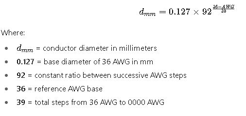
Formula 1: Converting AWG to Diameter (in mm)
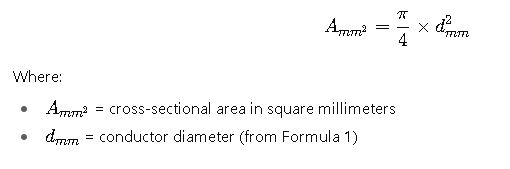
Formula 2: Converting AWG to Cross-Sectional Area (mm²)
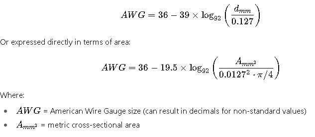
Formula 3: Converting mm² to AWG
Because AWG is logarithmic, the inverse formula is required:
Formula 4: Conversion via Circular Mils (CM)
In North American practice, wire area is often expressed in circular mils (CM):
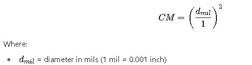
To convert mm² to circular mils:
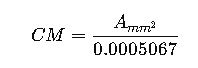
This formula is frequently used when comparing IEC conductors to NEMA/UL listed equivalents.
Explanation of Variables
- AWG – logarithmic gauge system, where smaller numbers indicate larger conductors.
- mm² (Cross-sectional area) – metric measurement directly proportional to conductor size.
- Diameter (mm) – physical conductor diameter (without insulation).
- Circular Mils (CM) – North American unit of area (diameter in mils squared).
- Logarithmic ratio (92) – defines AWG scaling between steps.
- 0.127 mm – reference base for 36 AWG diameter.
Real-World Engineering Applications
To see how these formulas and tables apply in practice, let’s work through two case studies commonly encountered in international projects.
Case Study 1: Industrial Motor Connection (IEC to NEMA Conversion)
Scenario:
A German OEM designs a motor system requiring 16 mm² copper conductors for power leads. The motor will be exported to the United States, where UL-listed cables are required, expressed in AWG/NEMA sizes.
Step 1: Identify IEC conductor size
- 16 mm² (metric standard)
Step 2: Find equivalent AWG size
From the conversion table:
- 16 mm² ≈ 5 AWG (cross-sectional ~33,178 CM)
Step 3: Verify ampacity requirements
- According to IEC 60364, 16 mm² copper cable typically supports ~76 A (installation dependent).
- NEC Table 310.16 lists 5 AWG copper (THHN insulation) at ~85 A (75°C rating).
Step 4: Conclusion
The closest NEMA equivalent is 5 AWG copper THHN, ensuring compliance with UL standards while meeting the OEM’s electrical requirements.
Case Study 2: Renewable Energy DC Busbar Design (NEMA to IEC Conversion)
Scenario:
A U.S. solar project specifies 500 kcmil conductors for a central inverter DC bus. The EPC contractor, sourcing cables in Europe, requires the equivalent size in metric (IEC).
Step 1: Identify NEMA conductor size
- 500 kcmil (≈ 500,000 CM)
Step 2: Convert to mm²
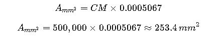
Step 3: Select IEC standard size
- The nearest standard size is 240 mm² (next available: 300 mm²).
Step 4: Verify ampacity
- NEC (500 kcmil Cu, 75°C THHN): ~380 A
- IEC 60364 (240 mm² Cu, buried direct, standard conditions): ~365–385 A
Step 5: Conclusion
The IEC equivalent is 240 mm², which aligns closely with the NEC ampacity, validating its suitability.
Advanced Technical Considerations for mm² to AWG Conversion
While the mathematical conversion is essential, real-world engineering requires far more than simple equivalence. Several key aspects must be evaluated to ensure that the chosen conductor size meets regulatory and operational requirements.
Voltage Drop and Efficiency
One of the most common engineering mistakes is selecting a conductor purely based on ampacity without considering voltage drop. In long cable runs—such as in wind farms, data centers, or industrial automation plants—voltage drop can become significant.
- IEC generally limits voltage drop to 3% for feeders and 5% for final circuits.
- NEC recommends voltage drop under 3% per branch circuit and 5% total.
Even if an mm² and AWG conversion matches in cross-sectional area, conductor resistance per kilometer can differ due to manufacturing tolerances and stranding. Engineers should always verify Ω/km values from manufacturer datasheets.
Harmonic Distortion and Skin Effect
In modern electrical systems, especially those with variable frequency drives (VFDs), UPS systems, or LED lighting, harmonic distortion increases conductor heating. While both IEC and NEMA provide ampacity tables, neither explicitly accounts for harmonics.
For high harmonic environments:
- Oversizing by at least one AWG step (or 2–4 mm²) is common.
- Parallel conductors may be used instead of a single large conductor to mitigate skin effect, where AC current tends to concentrate on the surface of conductors at higher frequencies.
Thermal Rating Differences
IEC and NEMA tables are based on different ambient temperature assumptions.
- IEC ampacity ratings often assume 30°C ambient air.
- NEC ampacity tables usually assume 30°C ambient, but the application of correction factors for higher temperatures is mandatory.
This means a direct mm² to AWG conversion may still require derating in hot environments such as rooftop solar arrays, oil refineries, or desert substations.
Stranding and Flexibility
Another important distinction between IEC and NEMA conductors is stranding class:
- IEC conductors often follow Class 2 (solid or stranded) or Class 5 (flexible) stranding.
- NEMA (UL-listed) conductors generally use Class B stranding, which is less flexible.
This difference is critical in applications such as robotics, aerospace, and marine systems, where bending radius and flexibility matter as much as ampacity.
Fire and Safety Standards
Both IEC and NEMA enforce rigorous safety standards, but the metrics differ:
- IEC cables may carry designations like LSZH (Low Smoke Zero Halogen) or CPR (Construction Products Regulation) classes for flame retardancy.
- NEMA/UL conductors are classified by insulation type: THHN, XHHW, RHH/RHW, MTW, each with different temperature and fire ratings.
When converting mm² to AWG, selecting the right insulation standard is just as important as conductor size.
Extended Conversion Table with Intermediate Sizes
To provide engineers and technicians with more precise reference points, here’s an expanded table including non-standard intermediate values. This is especially useful when dealing with decimal AWG results from calculators.
Table 2: Extended Metric to AWG Reference (Intermediate Sizes)
| Metric Size (mm²) | Approx. Diameter (mm) | Equivalent AWG | Common NEMA Sizes |
|---|---|---|---|
| 0.14 mm² | 0.42 mm | 26 AWG | Control wiring |
| 0.34 mm² | 0.65 mm | 22 AWG | Signal circuits |
| 0.75 mm² | 0.98 mm | 18 AWG | Lighting control |
| 1.25 mm² | 1.25 mm | 16.5 AWG | Non-standard |
| 2.0 mm² | 1.60 mm | 14.5 AWG | Non-standard |
| 3.5 mm² | 2.10 mm | 12.3 AWG | Non-standard |
| 5.0 mm² | 2.52 mm | 10.5 AWG | Non-standard |
| 8.0 mm² | 3.19 mm | 8.4 AWG | Non-standard |
| 14 mm² | 4.20 mm | 5.6 AWG | Between 6 and 5 AWG |
| 20 mm² | 5.05 mm | 4.2 AWG | Between 4 and 3 AWG |
| 30 mm² | 6.20 mm | 2.6 AWG | Between 3 and 2 AWG |
| 75 mm² | 9.75 mm | 1/0.5 AWG | Between 1/0 and 2/0 |
| 150 mm² | 13.70 mm | 300 kcmil | NEC standard |
| 500 mm² | 25.00 mm | 1000 kcmil | NEC standard |
This table shows that not every metric size has a direct AWG equivalent. In such cases, engineers must round up to the nearest available AWG to ensure capacity is not undersized.


