The correct design and selection of lightning arresters (SPDs) ensures electrical system safety reliability. IEC 60099, IEC 62305, and IEEE C62 provide methods to calculate, select, and verify.
Lightning Arrester for Surge Protection Calculator – IEC, IEEE
Compute recommended MCOV (Uc) and Rated Voltage (Ur) for MOV arresters.
What does this calculator do?
Formulas used
Earth-fault factor: k (p.u.) → Uc ≥ k · VL-N,max.
Typical mapping: effectively grounded k≈1.0, resistance grounded k≈1.4, isolated/resonant/delta k≈1.73.
Rated voltage (IEC): Ur ≈ 1.25 · Uc (common manufacturer ratio).
How do I check protection margin?
When to choose higher Uc/Ur?
Comprehensive Tables of Common Lightning Arrester Values (IEC, IEEE)
Below are structured reference tables containing commonly used values in arrester selection and surge protection design. These tables reflect IEC 60099-4 (Metal-Oxide Surge Arresters) and IEEE C62.11 guidelines.
Table 1. Rated Voltage Levels for Surge Arresters (IEC/IEEE)
| Arrester Class | System Nominal Voltage (kV) | Rated Arrester Voltage Ur (kV rms) | Maximum Continuous Operating Voltage Uc (kV rms) | Common Application |
|---|---|---|---|---|
| Distribution Class | 3.3 – 36 kV | 3 – 30 kV | 2.55 – 24 kV | Medium-voltage substations, feeders |
| Intermediate Class | 36 – 72.5 kV | 30 – 60 kV | 24 – 50 kV | Subtransmission networks |
| Station Class | 72.5 – 420 kV | 60 – 360 kV | 50 – 288 kV | Transmission substations |
| EHV Class | 420 – 800 kV | 360 – 660 kV | 288 – 528 kV | Extra-high voltage grids |
Table 2. Typical Protective Levels of Surge Arresters
| Arrester Class | Residual Voltage at 10 kA (kV peak) | Protective Ratio (Ures/Ur) | Energy Absorption Capability (kJ/kV Ur) |
|---|---|---|---|
| Distribution | 1.8 – 2.2 × Ur | 1.8 – 2.2 | 2 – 4 |
| Intermediate | 1.7 – 2.0 × Ur | 1.7 – 2.0 | 3 – 6 |
| Station | 1.6 – 1.9 × Ur | 1.6 – 1.9 | 6 – 12 |
| EHV | 1.5 – 1.8 × Ur | 1.5 – 1.8 | 10 – 20 |
Table 3. Common Impulse Current Waveforms Defined by IEC/IEEE
| Surge Type | Waveform (µs) | Current Amplitude (kA) | Application / Standard Reference |
|---|---|---|---|
| Lightning Impulse (LI) | 8/20 | 5, 10, 20, 40, 65 | IEC 60060-1, IEC 61643 |
| Switching Impulse (SI) | 30/60 | 500 – 2000 A | IEC 60099-4 (HV arresters) |
| High Current Impulse | 4/10 | 65 – 100 kA | IEEE C62.11 duty cycle testing |
| Temporary Overvoltage (TOV) | >1000 ms | System dependent | IEC 60099-5 application guide |
Table 4. Recommended Safety Margins Between Uc and System Voltages
| System Nominal Voltage (kV rms) | Maximum Phase-to-Ground Voltage (kV rms) | Recommended Uc (kV rms) | Safety Factor |
|---|---|---|---|
| 11 kV | 6.35 | 9 – 10 | 1.4 – 1.6 |
| 33 kV | 19.05 | 24 – 27 | 1.3 – 1.5 |
| 132 kV | 76.2 | 96 – 105 | 1.25 – 1.35 |
| 220 kV | 127 | 165 – 180 | 1.3 – 1.4 |
| 400 kV | 231 | 288 – 312 | 1.25 – 1.35 |
Key Formulas in Lightning Arrester Selection (IEC/IEEE)
The following equations represent the foundation of arrester design and selection. Each formula is aligned with IEC 60099 and IEEE C62 guidelines.
1. Maximum Continuous Operating Voltage (Uc)
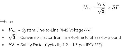
Explanation: Uc ensures the arrester can continuously withstand the system’s normal and temporary overvoltages.
2. Arrester Rated Voltage (Ur)
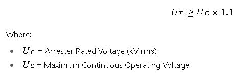
Explanation: Provides a margin ensuring the arrester withstands stresses during TOV conditions.
3. Protective Level (Ures)
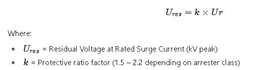
Explanation: Determines how effectively the arrester clamps surge overvoltages.
4. Energy Absorption Capability (W)
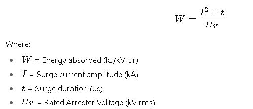
Explanation: Defines the arrester’s ability to dissipate energy without failure.
5. Temporary Overvoltage (TOV) Withstand
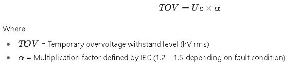
Explanation: Ensures the arrester survives abnormal system events such as earth faults or load rejection.
6. Discharge Current Rating (In)
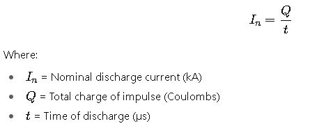
Explanation: Defines the capability to conduct surge currents of standard waveforms (commonly 8/20 µs).
Real-World Application Examples of Lightning Arrester Selection and Calculation
The following case studies demonstrate practical engineering applications of the Lightning Arrester for Surge Protection Calculator following IEC and IEEE methodologies.
Case Study 1: 33 kV Distribution Substation Protection
System Data
- Nominal System Voltage: 33 kV (line-to-line)
- Maximum Phase-to-Ground Voltage: 19.05 kV
- Expected Temporary Overvoltage (TOV): 1.3 × phase voltage for 1 second
- Surge Environment: Lightning-prone area (isokeraunic level > 50 thunderstorm days/year)
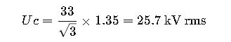
Step 1. Calculate Maximum Continuous Operating Voltage (Uc)
Step 2. Select Rated Arrester Voltage (Ur)
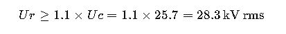
The closest standard arrester rating per IEC 60099-4 is 30 kV.
Step 3. Determine Protective Level (Ures)
For a distribution-class arrester (protective factor ~1.9):

Step 4. Validate Energy Absorption Capability
For a typical lightning surge of 10 kA, 8/20 µs:
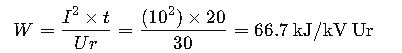
The selected distribution-class arrester supports 70 kJ/kV Ur, so it is sufficient.
Result: The 30 kV distribution-class arrester is suitable for this 33 kV substation, ensuring adequate protective margins against lightning-induced surges.
Case Study 2: 220 kV Transmission Substation Protection
System Data
- Nominal System Voltage: 220 kV (line-to-line)
- Maximum Phase-to-Ground Voltage: 127 kV
- Switching Overvoltages up to 1.7 p.u. of nominal
- Expected Impulse Current: 20 kA (8/20 µs)
- Arrester Class: Station-class
Step 1. Calculate Uc
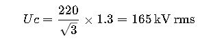
Step 2. Select Ur
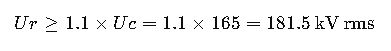
Nearest standard arrester rating: 180 kV rms or 198 kV rms. The 198 kV option provides safer margins.
Step 3. Protective Level (Ures)
For a station-class arrester (factor ~1.7):
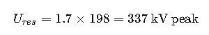
This ensures protection below the Basic Insulation Level (BIL) of 220 kV systems (~750 kV per IEC 60071-1).
Step 4. Energy Absorption Capability
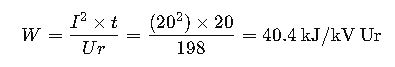
Station-class arresters for 220 kV typically handle >100 kJ/kV Ur, so the rating is safe.
Result: A 198 kV station-class arrester ensures effective surge protection for the 220 kV transmission substation, safeguarding transformers and switchgear from both lightning and switching surges.
Engineering Considerations for Surge Protection Design
When applying IEC and IEEE standards, engineers must evaluate multiple parameters beyond simple arrester voltage rating. These factors significantly influence arrester performance and long-term reliability.
1. Location of Installation
- Arresters should be installed as close as possible to the equipment they protect (e.g., transformer terminals).
- Long lead lengths increase protective voltage due to inductive reactance of connections.
Rule of Thumb: Keep arrester leads shorter than 1 meter where possible (IEEE C62.22).
2. Coordination with Insulation Levels
- IEC 60071-1 defines insulation coordination levels such as BIL (Basic Insulation Level).
- Arrester protective level (Ures) must be at least 20% lower than equipment BIL to guarantee safe clamping.
3. Temporary Overvoltages (TOV)
- Caused by earth faults, load rejection, or resonance phenomena.
- Arrester must withstand the system’s TOV curve for at least 1–10 seconds.
- IEC 60099-5 provides TOV withstand values for various system configurations.
4. Energy Capability and Duty Cycle
- Arresters experience multiple surges over their lifetime.
- IEEE C62.11 defines a duty cycle test (15 impulses of 10 kA, 8/20 µs) to confirm endurance.
5. Earthing and Grounding Resistance
- Surge arresters are only as effective as the grounding system.
- IEEE Std 80 recommends grounding resistance <1 Ω for substations.
- Poor grounding increases residual voltage and reduces protection effectiveness.
Advanced Example: Parallel Operation of Arresters
In EHV substations (>400 kV), sometimes two arresters are placed in parallel for increased current-handling capacity. According to IEC 60099-5:
- Parallel operation requires equal sharing of surge currents.
- Typically only used in high-energy installations such as UHV DC converter stations.