Inrush current is the sudden surge of electrical current occurring when equipment is initially energized. It critically impacts motors, transformers, and breakers, requiring accurate calculations for protection and proper system sizing.
Inrush Current Calculator – IEEE/IEC
How to use the Inrush Factor?
Duration?
Formula used
Common Inrush Current Values
The inrush current varies depending on the type of equipment and its design. Below are some typical inrush current values for various electrical devices:
Table 1: Typical Inrush Current Values
| Equipment Type | Inrush Current (times FLC) | Duration (ms) | Notes |
|---|---|---|---|
| Standard AC Motors | 6–8 | 100–200 | Direct-On-Line (DOL) starting method |
| Star-Delta Motors | 2–3.5 | 100–200 | Reduced starting current |
| Soft-Start Motors | 1.5–3 | 100–200 | Gradual increase in voltage |
| Transformers | 5–10 | 100–200 | Initial energizing surge |
| Fluorescent Lamps | 1.5–2.5 | 10–50 | Initial lamp ignition |
| Incandescent Lamps | 10–14 | 10–50 | Cold filament resistance |
| Capacitor Banks | 10–12 | 10–50 | Switching transients |
Note: FLC refers to Full Load Current.
Formulas for Calculating Inrush Current
Calculating inrush current involves understanding the factors that contribute to the initial surge. Below are key formulas and explanations:
1. Transformer Inrush Current
The inrush current for transformers can be estimated using the following formula:
I_inrush = √2 × I_rated
Where:
- I_inrush = Inrush current (Amps)
- I_rated = Rated current of the transformer (Amps)
Note: The factor √2 accounts for the peak value of the sinusoidal waveform.
2. Motor Inrush Current
For motors, especially during Direct-On-Line (DOL) starting, the inrush current can be approximated as:
I_inrush ≈ 6–8 × I_full_load
Where:
- I_inrush = Inrush current (Amps)
- I_full_load = Full load current of the motor (Amps)
Note: This multiplier varies based on motor design and starting method.
3. Lamp Inrush Current
For incandescent lamps, the inrush current is influenced by the cold resistance of the filament:
I_inrush = V_supply / R_cold
Where:
- I_inrush = Inrush current (Amps)
- V_supply = Supply voltage (Volts)
- R_cold = Cold resistance of the filament (Ohms)
Note: The cold resistance is significantly lower than the hot resistance, leading to a higher inrush current.
Real-World Examples
Example 1: Motor Start-Up Analysis
Consider a 15 kW, 400 V, 50 Hz three-phase induction motor. The full-load current (FLC) can be calculated as:
I_full_load = (P × 1000) / (√3 × V × PF)
Where:
- P = Power (kW)
- V = Voltage (Volts)
- PF = Power factor (assumed to be 0.85)
Substituting the given values:
I_full_load = (15 × 1000) / (√3 × 400 × 0.85) ≈ 26.5 A
Using the inrush current multiplier for DOL starting (6–8 times FLC):
I_inrush ≈ 6 × 26.5 A = 159 A
Note: The actual inrush current may vary based on motor design and starting method.
Example 2: Transformer Energizing
For a 100 kVA, 11 kV/400 V transformer, the rated current on the low-voltage side is:
I_rated = (S × 1000) / (√3 × V)
Where:
- S = Apparent power (kVA)
- V = Voltage (Volts)
Substituting the given values:
I_rated = (100 × 1000) / (√3 × 400) ≈ 144.3 A
Using the inrush current formula:
I_inrush = √2 × 144.3 A ≈ 203.5 A
Note: The inrush current is typically higher during transformer energizing due to magnetizing inrush.
Impact on System Design
Understanding inrush current is vital for:
- Equipment Sizing: Ensuring that transformers, circuit breakers, and other equipment can handle the initial surge without damage.
- Protection Coordination: Setting protection devices to differentiate between inrush currents and fault conditions to prevent unnecessary tripping.
- System Stability: Minimizing voltage dips and flicker that can affect sensitive equipment during inrush events.
Advanced Formulas and Considerations for Inrush Current
Inrush current is influenced by several factors beyond the basic formulas provided earlier. These include transformer saturation, motor winding resistance, supply voltage variations, and ambient temperature. Understanding these variables is critical for accurate prediction.
1. Transformer Saturation Effects
When a transformer is energized, the core may reach magnetic saturation depending on the flux at the moment of switching. This can dramatically increase inrush current.
Formula:
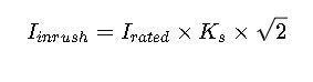
Where:
- I_inrush = Peak inrush current (A)
- I_rated = Rated current of the transformer (A)
- K_s = Saturation factor (typical range: 2–12, depending on transformer design and switching instant)
Explanation: The saturation factor accounts for the nonlinear behavior of the magnetic core. A transformer switched at zero flux can experience the highest inrush, whereas switching near the peak flux reduces it.
2. Motor Starting with Reduced Voltage Methods
While DOL motors have inrush multipliers of 6–8× FLC, reduced voltage starters, such as star-delta or soft starters, reduce the initial current significantly.
Formula for Star-Delta Start:

- star_reduction_factor ≈ 0.58 (depends on voltage reduction ratio)
- Duration: Typically 200–300 ms
Explanation: The reduced voltage decreases the initial torque, which is why the current is lower and more manageable for the supply system.
3. Capacitor Bank Switching
When switching large capacitor banks, the inrush can be high due to charging of the capacitors.
Formula:
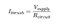
Where:
- V_supply = Applied voltage (V)
- R_circuit = Series resistance (Ω)
- Duration: Typically 1–20 ms depending on the circuit damping
Tip: Adding pre-insertion resistors or using controlled switching can significantly reduce the transient current.
Additional Real-World Examples
Example 3: Capacitor Bank Energization
A 400 kVAR capacitor bank rated for 400 V is switched directly to the network. The series resistance of the supply circuit is 0.1 Ω.

This very high current requires the use of pre-insertion resistors or controlled switching to avoid damage to the capacitor and upstream equipment.
Example 4: Fluorescent Lamp Circuit
A lighting circuit with 100 fluorescent lamps, each drawing 0.5 A full load current, is energized simultaneously. The inrush multiplier for fluorescent lamps is 2×.

This transient can trip upstream protection if not properly coordinated.
Best Practices for Managing Inrush Current
- Correct Equipment Sizing
Always choose circuit breakers and fuses that can withstand the maximum expected inrush without nuisance tripping. - Controlled Switching
Use devices such as soft starters, pre-insertion resistors, or zero-crossing switches to minimize peak currents. - Sequential Start
Avoid simultaneous energization of large motors, transformers, or capacitor banks. - Monitoring and Logging
Install power quality meters to record inrush events and adjust protection or control strategies. - Compliance with Standards
Follow IEEE and IEC standards such as:- IEEE Std 141 (Red Book) – Electric Power Distribution
- IEC 60947 – Low-voltage switchgear
- IEC 60076 – Power Transformers
Extended Tables for Engineers
Table 2: Motor Inrush Current Multipliers by Type
| Motor Type | DOL Multiplier | Star-Delta Multiplier | Soft Starter Multiplier | Notes |
|---|---|---|---|---|
| Squirrel Cage Induction | 6–8 | 2–3 | 1.5–3 | Most common industrial motors |
| Slip Ring Induction | 5–7 | 2–3 | 1.5–2.5 | External resistors can reduce |
| Synchronous | 4–6 | 2–3 | 1.2–2 | Excitation method affects peak |
| Permanent Magnet | 3–5 | N/A | 1.2–2 | Typically lower inrush |
Table 3: Transformer Inrush Factors
| Transformer Type | K_s (Saturation Factor) | Notes |
|---|---|---|
| Dry-type | 4–8 | Core material and size-dependent |
| Oil-immersed | 6–12 | High magnetization inrush possible |
| High-voltage | 2–6 | Switching instant critical |