Arc-flash risk analysis is essential in electrical safety, helping engineers calculate workers’ potential thermal exposure. NFPA 70E and IEEE 1584 define incident energy in cal/cm², determining PPE categories and boundaries.
Incident Energy Calculator — NFPA 70E / IEEE (IEEE-1584)
Estimate arc-flash incident energy (cal/cm² & J/cm²) using IEEE-1584 empirical method (0.208–1 kV branch). For design or legal work, verify with full IEEE 1584 / NFPA 70E and a qualified engineer.
What method does this calculator use?
Units and outputs
For engineering/legal use
Understanding Incident Energy According to NFPA 70E and IEEE 1584
- Incident energy: The amount of thermal energy impressed on a surface, at a specific distance, from an arc fault event.
- Measured in: cal/cm².
- Importance: Determines the severity of burns and establishes PPE requirements.
Both NFPA 70E (workplace electrical safety) and IEEE 1584 (arc-flash calculation guide) provide the basis for performing accurate calculations.
Extensive Tables of Common Incident Energy Values
Below are reference tables with values often encountered when using incident energy calculators. These values consider typical system voltages, fault currents, clearing times, and working distances based on IEEE 1584 and NFPA 70E application ranges.
Table 1. Common Incident Energy Values by Fault Current and Clearing Time (600 V class systems)
| Fault Current (kA) | Clearing Time (cycles) | Working Distance (mm) | Incident Energy (cal/cm²) |
|---|---|---|---|
| 10 kA | 6 cycles (0.1 s) | 457 mm (18 in) | 1.2 cal/cm² |
| 10 kA | 12 cycles (0.2 s) | 457 mm | 2.3 cal/cm² |
| 20 kA | 6 cycles | 457 mm | 2.8 cal/cm² |
| 20 kA | 12 cycles | 457 mm | 5.1 cal/cm² |
| 30 kA | 6 cycles | 457 mm | 4.5 cal/cm² |
| 30 kA | 12 cycles | 457 mm | 8.9 cal/cm² |
| 40 kA | 6 cycles | 457 mm | 6.3 cal/cm² |
| 40 kA | 12 cycles | 457 mm | 12.5 cal/cm² |
| 50 kA | 6 cycles | 457 mm | 8.5 cal/cm² |
| 50 kA | 12 cycles | 457 mm | 16.7 cal/cm² |
Table 2. PPE Categories by Incident Energy (per NFPA 70E 2021)
| Incident Energy (cal/cm²) | PPE Category | Typical Clothing Requirements |
|---|---|---|
| 1.2 – 4 cal/cm² | Category 1 | Arc-rated shirt and pants, face shield |
| 4.1 – 8 cal/cm² | Category 2 | Arc-rated jacket, balaclava, face shield |
| 8.1 – 25 cal/cm² | Category 3 | Arc-rated flash suit, hood, gloves |
| 25.1 – 40 cal/cm² | Category 4 | Heavy arc-rated flash suit, hood, gloves |
| >40 cal/cm² | Not for work | No PPE ensures survival |
Table 3. Typical System Parameters and Their Impact on Incident Energy
| Parameter | Typical Range | Impact on Incident Energy |
|---|---|---|
| System Voltage | 208 – 15,000 V | Affects arc duration and current |
| Fault Current (Ibf) | 5 – 65 kA | Higher fault current increases incident energy |
| Clearing Time (t) | 0.03 – 2.0 s | Longer clearing time dramatically increases energy |
| Working Distance (D) | 305 – 910 mm | Greater distance reduces incident energy |
| Electrode Configuration | VCB, VCBB, HCB, HOA | Geometry influences arc development |
| Equipment Type | MCC, switchgear, panels | Enclosure size and material alter results |
Core Formulas for Incident Energy Calculations (IEEE 1584-2018)
The IEEE 1584-2018 standard introduced a revised model for arc-flash incident energy, covering 208 V to 15 kV systems.
The general formula:
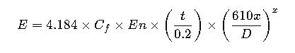
Where:
- E = Incident Energy (J/cm², then converted to cal/cm² by dividing by 4.184).
- Cf = Calculation factor (1.0 for voltages > 1 kV; 1.5 for < 1 kV).
- En = Normalized incident energy at 0.2 s and 610 mm distance (J/cm²).
- t = Arcing time (s).
- D = Working distance (mm).
- x = Distance exponent (empirical, usually between 1.0–1.5 depending on enclosure and system).
Arcing Current Equation
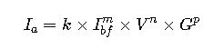
Where:
- Ia = Arcing current (kA).
- Ibf = Bolted fault current (kA).
- V = System voltage (kV).
- G = Gap between conductors (mm).
- k, m, n, p = Empirical constants from IEEE 1584 depending on electrode configuration.
Variables and Typical Values
| Variable | Description | Common Values |
|---|---|---|
| Ibf | Bolted fault current | 10 – 65 kA |
| Ia | Arcing current | 50–90% of Ibf |
| V | Voltage | 208 – 15,000 V |
| G | Gap between conductors | 13 – 152 mm |
| t | Clearing time | 0.03 – 2.0 s |
| D | Working distance | 305 – 910 mm |
| x | Distance exponent | 1.0 – 1.5 |
| Cf | Calculation factor | 1.0 or 1.5 |
Practical Application of Incident Energy Calculations
While formulas provide the mathematical foundation, the true value of incident energy analysis lies in applying these methods to real-world electrical systems. Engineers and safety managers often encounter diverse scenarios ranging from industrial plants with high-capacity switchgear to smaller commercial panels.
Below are two detailed case studies that demonstrate how incident energy calculators based on NFPA 70E and IEEE 1584 are applied in practice.
Case Study 1: Motor Control Center (MCC) in a Manufacturing Plant
System Description:
- Voltage: 480 V, 3-phase.
- Bolted Fault Current: 25 kA.
- Conductor Gap: 32 mm.
- Working Distance: 457 mm (18 in).
- Protective Device Clearing Time: 0.15 s (9 cycles).
- Equipment: Metal-enclosed MCC.
Step 1: Determine Arcing Current
The calculator estimates the arcing current (Ia) as 85% of the bolted fault current due to equipment configuration and electrode orientation.
- Arcing current ≈ 21 kA.
Step 2: Apply Incident Energy Formula
The calculator normalizes the result at 0.2 s and 610 mm, then scales it based on actual clearing time and working distance.
Step 3: Calculate Incident Energy
Resulting incident energy ≈ 6.5 cal/cm² at 457 mm.
Step 4: Determine PPE Category
According to NFPA 70E, 6.5 cal/cm² requires PPE Category 2:
- Arc-rated clothing (≥ 8 cal/cm²).
- Arc-rated face shield or arc flash hood.
- Leather gloves and protective footwear.
Interpretation:
Although the system voltage is only 480 V, the relatively high fault current and moderate clearing time yield a significant hazard. Without proper arc-rated PPE, a worker would be at risk of severe burns.
Case Study 2: Medium-Voltage Switchgear in a Utility Substation
System Description:
- Voltage: 13.8 kV, 3-phase.
- Bolted Fault Current: 40 kA.
- Conductor Gap: 104 mm.
- Working Distance: 910 mm (36 in).
- Protective Device Clearing Time: 0.08 s (5 cycles).
- Equipment: Metal-clad switchgear.
Step 1: Determine Arcing Current
With medium-voltage systems, the arcing current is closer to the bolted fault current, approximately 90%.
- Arcing current ≈ 36 kA.
Step 2: Apply Calculator Model
Using IEEE 1584 empirical data for enclosed switchgear, normalized incident energy is scaled by working distance and clearing time.
Step 3: Calculate Incident Energy
Resulting incident energy ≈ 11.2 cal/cm² at 910 mm.
Step 4: Determine PPE Category
This places the hazard in PPE Category 3:
- Arc-rated flash suit with hood (≥ 25 cal/cm²).
- Insulated gloves and tools.
- Hearing protection and footwear.
Interpretation:
Even at longer working distances, medium-voltage systems present higher hazards due to higher fault currents. The shorter clearing time of protective relays helps reduce energy but still requires heavy PPE.
Arc-Flash Boundary Considerations
The arc-flash boundary (AFB) is the distance at which incident energy falls to 1.2 cal/cm²—the threshold for a second-degree burn on bare skin.
Typical examples:
- Low-voltage MCC (480 V, 20 kA, 0.1 s clearing time): AFB ≈ 0.9 m.
- Medium-voltage switchgear (13.8 kV, 35 kA, 0.08 s clearing time): AFB ≈ 2.5 m.
This concept defines how close a worker can approach without arc-rated PPE. Anyone working inside the boundary must wear protective clothing.
Key Factors That Influence Incident Energy
1. Clearing Time
The single most critical factor. Doubling clearing time typically doubles the incident energy. Protective relays and current-limiting breakers dramatically reduce exposure.
2. Working Distance
Incident energy reduces with distance, following an exponential decay. Extending working distance even a few inches can significantly lower exposure.
3. Electrode Configuration
- VCB (Vertical Conductors in a Box): Produces higher energy due to plasma confinement.
- HCB (Horizontal Conductors in a Box): Directs arc plasma outward, often yielding higher hazard at the worker’s face.
- Open-air faults: Lower incident energy compared to enclosed equipment.
4. System Voltage and Fault Current
While fault current magnitude is important, systems with very high currents may cause protective devices to trip faster, sometimes lowering total incident energy.
Engineering Controls to Reduce Incident Energy
Organizations implement various strategies to mitigate arc-flash hazards beyond PPE:
- Current-Limiting Breakers/Fuses
- Limit the let-through energy by interrupting arcs faster.
- Particularly effective in low-voltage MCCs.
- Arc-Flash Relays and Sensors
- Use light and current detection to trip breakers within milliseconds.
- Reduce incident energy to <1 cal/cm² in some cases.
- Remote Operation
- Workers operate breakers from a safe distance, outside the arc-flash boundary.
- System Design Optimization
- Lowering fault current by adding impedance (transformers, reactors).
- Coordination studies to ensure fast tripping of upstream protection.
Authoritative References and Further Reading
For professionals seeking official guidance, the following resources are essential: