The design of electrical distribution systems must ensure efficiency, reliability, and absolute safety under fault conditions. The National Electrical Code defines requirements for minimum AIC breaker ratings to safely interrupt potential catastrophic failures.
High Interrupting Capacity (AIC) Breaker Calculator — NEC
Calculate the minimum AIC (kA) required and get suggested commercial breaker interrupting ratings. For design and NEC compliance confirm with local authority having jurisdiction (AHJ).
What does AIC (kA) mean?
What input should I provide?
Formulas used
Recommended Rating = smallest commercial rating ≥ (Required AIC × (1 + margin)).
Margin (%) can be set explicitly for additional safety (e.g., 20%).
Disclaimer
What is High Interrupting Capacity (AIC)?
The AIC rating (sometimes called Interrupting Rating (IR) or Short-Circuit Current Rating (SCCR) for certain equipment) represents the maximum fault current a breaker can interrupt safely without failing.
It is expressed in amperes symmetrical RMS (A) or kiloamperes (kA) at a specified system voltage.
For example:
- A breaker rated 10 kA @ 240 V can safely interrupt 10,000 amps of fault current at 240 volts AC.
- If the available fault current exceeds this value, the breaker can explode or fail catastrophically, creating fire and arc-flash hazards.
NEC Requirements for AIC Rating
According to NEC Article 110.9 (Interrupting Rating):
Equipment intended to interrupt current at fault levels shall have an interrupting rating sufficient for the current that is available at the line terminals of the equipment.
This means:
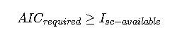
- The breaker’s AIC rating must be equal to or greater than the available short-circuit current (Isc) at the point of installation.
- If a breaker with insufficient AIC is used, it violates NEC and poses a severe safety hazard.
Typical Commercial AIC Ratings of Breakers
Circuit breakers are manufactured with standardized interrupting ratings based on UL 489 and ANSI C37.13.
Below is an extended reference table showing common AIC values available in the U.S. market.
Table 1 – Common Breaker AIC Ratings by Voltage Class
| Breaker Type | Typical Voltage Class | Standard AIC Ratings (kA RMS Sym) | Notes |
|---|---|---|---|
| Miniature Circuit Breaker (MCB) | 120/240 V AC | 5, 10, 22 kA | Residential, light commercial |
| Molded Case Circuit Breaker (MCCB) | 240 V AC | 10, 22, 25, 42, 65 kA | Commercial distribution panels |
| MCCB | 480 V AC | 14, 18, 25, 35, 42, 65, 100 kA | Industrial switchboards |
| MCCB | 600 V AC | 14, 18, 25, 35, 42, 65, 85, 100 kA | Higher-voltage distribution |
| Low-Voltage Power Circuit Breaker | 480–600 V AC | 65, 85, 100, 150 kA | Utility-grade protection |
| Medium Voltage Breaker | 2.4–15 kV | 25, 31.5, 40, 50, 63 kA | ANSI C37.06, utility systems |
| DC Rated Breakers | 125–600 V DC | 5, 10, 22, 50 kA | Data centers, solar, battery |
These are catalog ratings, and the selected AIC must always exceed the calculated available fault current.
Fundamental Formulas for High Interrupting Capacity (AIC)
The AIC rating calculation is essentially a short-circuit current analysis at the point where the breaker is installed.
Formula 1 – Available Fault Current (Isc)
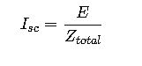
Where:
- Isc = Available short-circuit current (A RMS symmetrical)
- E = System line-to-line voltage (V)
- Ztotal = Total system impedance from source to fault (Ω)
Notes:
- Ztotal includes transformer impedance, conductor impedance, and source impedance.
- For three-phase systems:
Formula 2 – Short-Circuit Current at Transformer Secondary
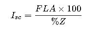
Where:
- FLA = Full Load Amps of transformer secondary
- %Z = Transformer impedance in %
This is one of the most commonly used quick methods in NEC-based fault current studies.
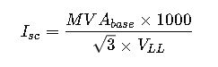
Formula 3 – Full Load Current of Transformer

Where:
- kVA = Transformer rating in kilovolt-amperes
- VLL = Line-to-line secondary voltage
Formula 4 – Available Fault Current at Service Entrance
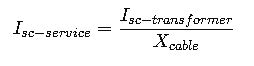
Where:
- Isc-transformer = Short-circuit current at transformer secondary
- Xcable = Factor considering conductor impedance (length, size, material, temperature)
Formula 5 – Required Breaker AIC Rating
Where:
- AICrequired = Minimum breaker interrupting rating (A RMS symmetrical)
- Isc-available = Maximum calculated available fault current
Detailed Variable Explanation
To ensure clarity, below is a breakdown of each critical parameter:
| Variable | Description | Common Range / Values |
|---|---|---|
| E | System line-to-line voltage | 120 V, 208 V, 240 V, 277 V, 480 V, 600 V |
| Ztotal | Equivalent impedance from source to fault | Depends on transformer %Z, cable length, utility |
| %Z | Transformer impedance percentage | 2% – 10% typical |
| kVA | Transformer capacity | 45, 75, 112.5, 150, 225, 300, 500, 750, 1000 kVA |
| FLA | Transformer full load amps | Varies with kVA and secondary voltage |
| Xcable | Cable impedance correction factor | 0.7 – 0.95 typical |
| Isc | Available fault current | From 1,000 A to >100,000 A |
| AICrequired | Breaker minimum interrupting rating | Must be ≥ Isc |
Extended Table of Typical Fault Current Values
The following table shows approximate available fault currents for common transformer sizes and secondary voltages, assuming 5% impedance and negligible cable length.
This serves as a reference starting point for engineers.
Table 2 – Fault Current Reference (3-Phase, 5% Z Transformers)
| Transformer Size (kVA) | Voltage (V LL) | Full Load Amps (FLA) | Fault Current (Isc) (A) | Typical AIC Required (kA) |
|---|---|---|---|---|
| 45 kVA | 208 V | 125 A | 2,500 A | 10 kA |
| 75 kVA | 480 V | 90 A | 1,800 A | 10 kA |
| 112.5 kVA | 480 V | 135 A | 2,700 A | 10 kA |
| 150 kVA | 208 V | 416 A | 8,300 A | 10 kA |
| 225 kVA | 480 V | 271 A | 5,400 A | 10 kA |
| 300 kVA | 480 V | 361 A | 7,200 A | 10–22 kA |
| 500 kVA | 480 V | 601 A | 12,000 A | 22–35 kA |
| 750 kVA | 480 V | 902 A | 18,000 A | 25–42 kA |
| 1000 kVA | 480 V | 1202 A | 24,000 A | 35–65 kA |
| 2000 kVA | 480 V | 2405 A | 48,000 A | 65–100 kA |
Real-World Case Study 1 – Commercial Building Service Entrance
Imagine a medium-sized commercial building with a 480 V three-phase service, supplied by a 750 kVA transformer provided by the utility. The transformer impedance is typical at 5%, and the service entrance main breaker is rated at 1,200 A.
An electrical engineer performs a fault current study to determine the available short-circuit current at the service disconnect. Based on utility data and transformer size, the study indicates an available fault current close to 18,000 amperes.
Now, the main breaker must be selected to withstand this fault current. If a 10 kA breaker were used, it would fail catastrophically under a fault condition. Instead, the engineer specifies a breaker with a 25 kA interrupting rating at 480 V. This ensures full compliance with NEC 110.9 and provides a safe margin above the calculated available fault current.
This example demonstrates how a seemingly standard breaker could be dangerously undersized if interrupting capacity is ignored. By correctly applying NEC principles, the building avoids severe safety risks and potential violations during inspection.
Real-World Case Study 2 – Industrial Motor Control Center (MCC)
Consider an industrial facility operating heavy machinery, with multiple 2,000 kVA transformers feeding a motor control center (MCC) at 480 V. Each transformer has 5% impedance and supplies multiple large induction motors.
The available short-circuit current at the MCC bus is calculated to be above 45,000 amperes. Breakers installed inside the MCC must therefore have AIC ratings of at least 65 kA at 480 V.
In practice, standard molded-case breakers often top out at 35 kA or 42 kA. To handle higher fault currents, engineers may specify:
- High AIC molded-case breakers (65 kA or 100 kA ratings)
- Current-limiting fuses in series with breakers to reduce available fault current to within the breaker’s capability
- Power circuit breakers designed for utility-grade fault clearing
The solution in this case involved using 65 kA MCCBs, ensuring compliance with NEC and protecting workers from arc-flash hazards during fault conditions.
This example highlights how industrial facilities often require high-interrupting devices, and why coordination between utility data, transformer size, and breaker selection is critical.
Advanced Engineering Considerations in AIC Calculations
X/R Ratio and Asymmetrical Current
Short-circuit currents are not purely symmetrical. The X/R ratio (reactance-to-resistance ratio) of the system influences the asymmetrical component of fault current, which can significantly increase the first-cycle peak current.
Although breaker ratings are expressed in symmetrical RMS amperes, manufacturers test breakers with standard X/R ratios to ensure they can handle the additional stresses of asymmetrical fault currents.
Time-Current Coordination
When selecting breakers, engineers must also consider selective coordination with upstream and downstream devices. The breaker must not only have the correct AIC rating, but it must also trip selectively without unnecessarily shutting down other circuits. This is crucial in hospitals, data centers, and critical infrastructure.
Current-Limiting Devices
When available fault currents exceed the standard breaker ratings, current-limiting fuses or breakers are used to reduce the let-through energy. These devices clear the fault so quickly that the downstream breaker never experiences the full fault magnitude. This strategy allows the use of lower-AIC breakers in certain applications, provided the overall protective scheme is compliant with NEC.
Arc-Flash and Worker Safety
Beyond NEC compliance, high fault currents present a significant arc-flash hazard. A properly rated breaker not only prevents catastrophic equipment failure but also reduces the incident energy exposure to workers. Standards such as NFPA 70E provide guidelines for arc-flash calculations, PPE requirements, and safe work practices.
Common Mistakes in AIC Selection
- Relying only on catalog data without performing a short-circuit study.
- Assuming a 10 kA breaker is always adequate in commercial settings, which is often false.
- Ignoring transformer impedance values, leading to underestimation of available fault current.
- Not considering motor contribution, which can add thousands of amps during a fault.
- Failing to update breaker ratings after utility system upgrades that increase fault current.
Best Practices for NEC-Compliant Breaker Selection
- Always request fault current data from the utility provider before design.
- Perform a complete short-circuit and coordination study using software tools such as ETAP, SKM PowerTools, or EasyPower.
- Select breakers with interrupting ratings equal or greater than the calculated available fault current.
- Use current-limiting fuses where extremely high fault currents exist.
- Regularly update studies and breaker ratings when system loads or utility services change.
- Document AIC calculations clearly for compliance with NEC Article 110.9 and 110.10.
Extended Table – NEC Typical Breaker Applications by AIC Rating
| Application | Common Voltage | Typical Available Fault Current | Recommended Breaker AIC |
|---|---|---|---|
| Residential home service | 120/240 V | < 10,000 A | 10 kA |
| Small retail shop | 120/240 V | 10,000 – 22,000 A | 22 kA |
| Medium commercial building | 480 V | 15,000 – 25,000 A | 25 kA |
| Large commercial facility | 480 V | 25,000 – 42,000 A | 35–42 kA |
| Industrial MCC | 480 V | 40,000 – 65,000 A | 65 kA |
| Utility-scale facility | 480–600 V | 65,000 – 100,000 A | 100 kA |
| Medium voltage switchgear | 4.16–15 kV | 25,000 – 63,000 A | 40–63 kA |
This table is an excellent quick reference for engineers during preliminary design. Final breaker ratings must always be based on a detailed short-circuit study.