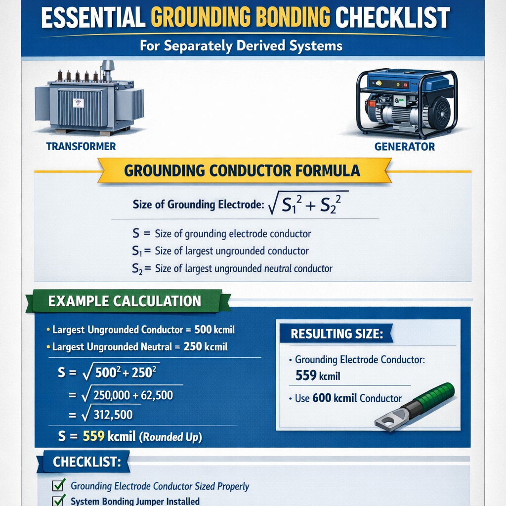
This checklist outlines essential grounding and bonding procedures for separately derived systems: transformers and generators. It targets engineers, inspectors, and contractors seeking code-compliant grounding, fault protection, and operational reliability assurance.
Minimum Bonding / Grounding Conductor Size Calculator for Separately Derived Systems (Transformers and Generators)
Scope and technical objective
This document provides a technical, code-oriented checklist for grounding and bonding of separately derived systems (SDS) — primarily transformers and generators — used in commercial and industrial installations. It focuses on practical verification steps, calculation methods, measurement techniques, and acceptance criteria to ensure personnel safety and correct operation of overcurrent devices, protection relays, and lightning/ surge mitigation components.
Key definitions and system types
- Separately Derived System (SDS): A system whose neutral is created by a device such as a transformer or generator and is not connected to another supply neutral at the same point (commonly defined by code, e.g., NEC 250.30).
- Grounding Electrode: Conductive object(s) in direct contact with the earth used to dissipate fault and lightning currents (ground rods, plates, concrete-encased electrodes, ground mats).
- Equipment Grounding Conductor (EGC): Conductor used to connect non-current-carrying metal parts of equipment to a grounding electrode or the grounding system.
- System Bonding Jumper (SBJ): A conductor that connects the grounded conductor of a separately derived system to the grounding electrode conductor or grounding electrode system.
- Solidly Grounded: System intentionally connected to earth without intentionally inserting impedance in the connection.
Applicable standards and authoritative references
- NFPA 70, National Electrical Code (NEC) — requirements for grounding separаtely derived systems, bonding jumpers, electrode connections. (https://www.nfpa.org/)
- IEEE Std 142 — Green Book: Recommended Practice for Grounding of Industrial and Commercial Power Systems. (https://standards.ieee.org/)
- IEEE Std 80 — Guide for Safety in AC Substation Grounding. (https://standards.ieee.org/)
- IEC 60364 — Electrical installations of buildings (international guidance). (https://www.iec.ch/)
- OSHA 29 CFR 1910 Subpart S — Electrical, for workplace safety requirements. (https://www.osha.gov/)
- Local utility interconnection guidelines and manufacturer installation manuals for transformers and generators.
Checklist overview — high level
- Verify whether the device is a separately derived system per code definition and manufacturer marking.
- Confirm neutral-to-ground bonding point location and whether bonding is required at the device.
- Identify grounding electrode(s) and their configuration (rods, plate, Ufer, counterpoise).
- Size system bonding jumper and EGCs using fault-current-based calculations and/or code tables.
- Verify continuity, integrity, and physical protection of all grounding/bonding conductors.
- Measure ground electrode resistance and validate against project acceptance criteria.
- Confirm coordination with overcurrent protection (clearing times) and relay settings.
- Document tests, measurements, calculations, and as-built connections.
Detailed checklist items and technical checks
1. Identify separately derived status
- Confirm whether neutral is derived from transformer secondary with no solid conductor connection to the system neutral upstream. If the neutral conductor is created at the transformer and not connected to the supply neutral, the transformer secondary is an SDS.
- Check transfer switches: a transfer switch that switches the neutral conductor may make a generator non-separately-derived if the neutral remains solidly connected. Confirm manufacturer documentation.
2. Neutral-ground bonding at SDS
- Neutral of the SDS must be bonded to the grounding electrode system at the SDS point of supply using a system bonding jumper (SBJ) sized appropriately.
- Mark the bonding point clearly. Where multiple electrodes exist, the SBJ must connect to the electrode system conductor or grounding electrode conductor.
3. Grounding electrode system and electrode conductor routing
- Locate electrodes close to the SDS but avoid long, unnecessary runs of the grounding electrode conductor (GEC).
- Choose electrode type based on soil conditions and site constraints: driven rods, concrete encased electrode (Ufer), plate electrodes, ground grid.
- Use corrosion-resistant conductors and provide mechanical protection (conduit, burial depth) as required by code.
4. Equipment grounding conductor (EGC) sizing and bonding jumper calculations
Use fault current calculations and adiabatic heating rules to determine minimum cross-sectional area required to withstand available fault energy until protective devices clear.
Fundamental formulas (HTML-only):
- Explain variables:
- I_fault — prospective fault current in amperes (A).
- V — nominal phase-to-ground or phase-to-phase voltage (V) depending on fault type.
- Z_total — total loop impedance between source, fault point, and return path (ohms).
- S_required — minimum conductor cross-sectional area (mm²) required to withstand thermal stress during fault.
- t — prospective fault clearing time (s) determined by relay/fuse characteristics or upstream device operation time.
- k — material constant (depends on conductor material and permissible temperature rise). Typical k (approximate): copper k ≈ 115, aluminum k ≈ 95. Verify with applicable code/standard.
- Typical values:
- k (copper) = 115 (use manufacturer/standard values for final design).
- t = 0.1 to 2 s depending on breaker/fuse characteristics; typical MCCB clearing times 0.1–0.5 s, fused protection for transformer secondary may be faster.
5. Ground electrode resistance and acceptable values
Measure electrode resistance with fall-of-potential method or clamp-on ground tester for large grids. Typical target values depend on risk assessment and code or project specs:
- Desirable single-site target: ≤ 25 Ω is a common project target for general building safety. Lower values (≤ 5 Ω) are specified for sensitive installations (substations, hospitals) per IEEE/utility requirements.
- Use multiple electrodes, ground mats, or chemical electrodes in high resistivity soils to reduce resistance.
Practical formulas and physical models
Ground rod approximate DC resistance
Use the practical approximation for a single vertical rod partially extending above soil:
R_rod ≈ (ρ / (2π L)) * (ln(8L/d) - 1)
- Variables:
- R_rod — approximate DC resistance of a single round driven rod (ohms).
- ρ (rho) — soil resistivity (ohm·m).
- L — length of rod (m).
- d — rod diameter (m).
- Typical values:
- ρ = 100 ohm·m (clay/loam), ρ = 1000 ohm·m (sandy gravel), ρ = 10,000 ohm·m (dry rock).
- L = 3 m (10 ft), d ≈ 0.016 m (5/8 in).
Prospective fault current (three-phase) at transformer secondary
For a transformer, approximate prospective short-circuit current at secondary can be estimated as:
- Variables:
- I_sc — estimated short-circuit current at the transformer's secondary (A).
- kVA — transformer rated kilovolt-amperes.
- V_secondary — secondary line-to-line voltage (V).
- %Z — transformer per-unit impedance in percent (%).
- Typical values: %Z often ranges from 2.5% to 6% for distribution transformers; conservative design uses manufacturer data.
| AWG / Metric | Cross-section (mm²) | Typical ampacity (A) | Common EGC usage (per NEC) |
|---|---|---|---|
| 14 AWG | 2.08 | 15 | Branch circuits light loads |
| 10 AWG | 5.26 | 30 | Small branch/circuits |
| 6 AWG | 13.3 | 65–75 | Feeder EGCs, small motors |
| 1 AWG | 42.4 | 130–150 | Large feeders, EGCs for high currents |
| 1/0 AWG | 53.5 | 150–175 | Medium transformer connections |
| 4/0 AWG | 107.2 | 230–260 | Large feeders, transformer grounds |
| Soil Type | Typical ρ (ohm·m) | Expected single 3m rod R (approx) | Mitigation |
|---|---|---|---|
| Wet clay | 20–50 | 6–16 Ω | Single rod or small grid often sufficient |
| Loam | 50–200 | 16–67 Ω | Multiple rods, ring electrode |
| Sandy soil | 200–1000 | 67–335 Ω | Deep rods, counterpoise, chemical electrodes |
| Rock | >1000 | >335 Ω | Chemical electrodes, driven deep rods, ground grid |
Testing and commissioning procedures
Continuity and bonding verification
- Visual inspection: confirm bolted connections, anti-oxidant on aluminum terminations (if permitted), and appropriate torque on bolts per manufacturer.
- Continuity test: measure DC resistance of SBJ and EGCs; typical readings should be near zero ohms (milliohms to tens of milliohms depending on length).
- Verify labeling: bonding jumpers, neutrals, and ground conductors are clearly labeled and documented.
Earth resistance measurement
- Use the fall-of-potential method for single rods and grids; for large meshes use clamp-on earth testers capable of testing driven rods and grids in parallel.
- Measure at different seasons and moisture conditions; note that rainy conditions yield lower resistances than dry summer conditions.
Loop impedance and prospective fault current verification
- Measure end-to-end loop impedance (hot‑to‑ground) at relevant points to verify protective device clearing times will operate within expected limits.
- Compare measured I_fault = V / Z_loop to calculated values and ensure protective devices have the required interrupting ratings and discrimination.
Operational considerations and special cases
Multiple transformers/parallel systems
- When multiple transformers feed the same bus, coordinate neutral bonding and grounding electrode connections to prevent unintended parallel neutral paths and circulating currents.
- Ensure that each separately derived source has a clear, single neutral-to-ground bonding point or that system design intentionally bonds neutrals consistent with code and utility interconnection rules.
Generators and transfer switches
- Open-transition vs solid-transfer: verify whether the neutral is switched. If the transfer switch switches the neutral, check whether the generator is or is not a separately derived system during transfer.
- Portable generators often bond neutral to frame; verify owner/operator requirements and field modifications do not inadvertently create objectionable currents.
Example calculations and worked examples
Example 1 — 250 kVA transformer, 480 V secondary, 5% impedance
Problem statement: A 250 kVA dry-type transformer provides a separately derived 480Y/277V secondary with %Z = 5%. Determine the prospective three-phase secondary short-circuit current, evaluate a required bonding jumper cross-section S using an assumed clearing time, and recommend conductor size.
Step 1 — Calculate prospective short-circuit current at secondary:
Substitute typical values:
Compute intermediate values:
Step 2 — Determine required conductor cross-section using adiabatic formula:
Assumptions:
- I_fault = 6014 A
- Assume clearing time t = 0.5 s (typical for upstream protective devices in distribution).
- k (copper) = 115 (typical conservative value; confirm with standard).
Step 3 — Select a standard conductor size: 36.99 mm² ≈ choose 50 mm² copper (approximately 1 AWG/1.5 AWG equiv depending on table) for margin and mechanical robustness. Confirm mechanical protection and bending radius. If project specifies AWG, 1 AWG (42.4 mm²) is the next common size; consider 1/0 AWG or 2/0 AWG if additional margin or parallel runs are desired.
Step 4 — Verify protective device clearing characteristics and manufacturer recommended bonding jumper sizes. Document calculation, assumptions, and measurement points for inspection.
Example 2 — Generator grounding and rod network design in sandy soil
Problem statement: A standby diesel generator rated 400 A at 480 V (still treated as separately derived when neutral is bonded at generator) will be installed on a site with sandy soil resistivity ρ = 1000 ohm·m. Site requires ground electrode resistance below 25 Ω. Use three 3 m rods spaced 3 m apart and estimate expected combined resistance. If insufficient, recommend mitigation.
Step 1 — Single rod resistance approximation with formula:
R_rod ≈ (ρ / (2π L)) * (ln(8L/d) - 1)
Assumptions:
- ρ = 1000 ohm·m
- L = 3 m
- d = 0.016 m (≈5/8 in)
Step 2 — Estimate combined resistance for three rods in parallel (approximation):
Ideal parallel for widely spaced rods reduces resistance approximately to R_combined ≈ R_rod / N if spacing >> length. With 3 rods: R_combined ≈ 334.9 / 3 = 111.6 Ω.
Result: 111.6 Ω >> target 25 Ω. Not acceptable.
Step 3 — Mitigation options:
- Increase the number of rods significantly (e.g., 12–20 rods with good spacing) — but this is often impractical in high resistivity soils.
- Use deep-driven rods (longer L), which reduce R roughly proportionally to 1/L; a 30 m driven rod is usually not practical.
- Install a conductive counterpoise or ground grid (buried mesh) around generator pad to increase contact area and lower resistance.
- Use chemically-enhanced electrodes (salt backfill, conductive concrete, or commercial ground enhancement materials) to reduce soil resistivity locally around electrodes.
Recommendation: For ρ = 1000 ohm·m, specify a buried ground grid or chemically enhanced electrodes sized by an electrical engineer to meet the 25 Ω target; re-measure after installation and adjust as necessary.
Documentation and acceptance criteria
- Document all calculations, assumptions, and measurement results: transformer data (%Z), relay/fuse curves, clearing times, soil resistivity logs, electrode dimensions and spacing, test dates and environmental conditions.
- Provide as-built single-line diagrams showing exact neutral bonding point, location and sizes of SBJ, EGCs, and GECs, plus electrode layout and test points.
- Acceptance: continuity tests within milliohm expectations, electrode resistance within project-specified limits, protective device coordination verified with measured loop impedances.
Inspection checklist for field engineers
- Confirm SDS status and neutral bond location per manufacturer marking and code.
- Verify SBJ and GEC sizes match calculations and code tables; check conductor materials and protective coatings.
- Validate mechanical connections: torque check, anti-seize on aluminum/copper transitions, proper washers and locknuts used.
- Measure and record earth resistance values and loop impedance at multiple points; capture photos and instrument serial numbers.
- Confirm protective device interrupting rating exceeds calculated prospective fault current.
- Ensure labeling and documentation are placed at the SDS (neutral bond notice, grounding electrode location, and testing location).
References and further reading
- National Fire Protection Association, NFPA 70: National Electrical Code — see sections related to grounding and bonding and separately derived systems (NEC Article 250). (https://www.nfpa.org/)
- IEEE Std 142 — IEEE Green Book: Recommended Practice for Grounding of Industrial and Commercial Power Systems. (https://standards.ieee.org/)
- IEEE Std 80 — Guide for Safety in AC Substation Grounding. (https://standards.ieee.org/)
- IEC 60364 series — International Standard for electrical installations. (https://www.iec.ch/)
- OSHA Electrical Standards — general workplace electrical safety requirements. (https://www.osha.gov/)
- Manufacturer transformer and generator installation guides — consult for neutral bonding instructions and recommended bonding jumper sizes.
Final practical remarks
- Always verify manufacturer guidance for neutral bonding and grounding for each transformer or generator model; manufacturer instructions can supersede typical assumptions where specified.
- When in doubt, consult local authority having jurisdiction (AHJ) and a licensed professional electrical engineer to resolve complex multi-source grounding issues and to sign off on engineered solutions.
- Document and retain test data for future maintenance and troubleshooting; soil resistivity and ground resistance change with seasons, so periodic retesting is good practice.