Grounding systems are essential for reliable substation operation, ensuring safety, protection, and proper electrical equipment performance. IEEE Std 80-2013 offers comprehensive grounding methodologies, safety criteria, and equations for effective substation grid design.
IEEE Std 80 Grounding Grid Calculator
Rg = ρ [ 1/LT + 1/√(20·A)(1 + 1/(1 + h√(20/A))) ]
GPR ≈ If · Rg
Vmesh = Ig·Rg·Km
Vstep = Ig·Rg·Ks
Common Values Used in Grounding Grid Calculations (IEEE 80 Reference)
The following tables summarize typical ranges and standard values frequently used in grounding grid design. These values are drawn from IEEE 80 and industry practice.
Table 1 – Typical Soil Resistivity Values
| Soil Type | Resistivity Range (Ω·m) | Common Value (Ω·m) |
|---|---|---|
| Clay (wet) | 10 – 50 | 25 |
| Clay (dry) | 100 – 300 | 200 |
| Loam (moist) | 20 – 100 | 60 |
| Sand (wet) | 50 – 300 | 150 |
| Sand (dry) | 500 – 2000 | 1000 |
| Gravel (wet) | 100 – 500 | 300 |
| Gravel (dry) | 1000 – 5000 | 3000 |
| Rock (granite, dry) | 2000 – 10000 | 5000 |
| Agricultural soil (fertile) | 20 – 150 | 70 |
Table 2 – Maximum Allowable Touch and Step Voltages (IEEE 80)
These values depend on body weight (50 kg or 70 kg assumption) and shock duration.
| Body Weight | Fault Duration (s) | Allowable Touch Voltage (V) | Allowable Step Voltage (V) |
|---|---|---|---|
| 50 kg | 0.25 | 430 | 1210 |
| 50 kg | 0.5 | 305 | 860 |
| 50 kg | 1.0 | 215 | 610 |
| 70 kg | 0.25 | 520 | 1460 |
| 70 kg | 0.5 | 370 | 1040 |
| 70 kg | 1.0 | 260 | 740 |
(Values from IEEE 80, Table 1 and Table 2, simplified for common use cases.)
Table 3 – Common Fault Current Values in Substations
| Voltage Level | Typical Fault Current (kA) | Range (kA) |
|---|---|---|
| 13.8 kV | 20 | 10 – 40 |
| 34.5 kV | 25 | 15 – 50 |
| 69 kV | 30 | 20 – 60 |
| 115 kV | 40 | 20 – 70 |
| 230 kV | 50 | 30 – 80 |
| 500 kV | 60 | 40 – 100 |
Core Formulas in Grounding Grid Calculation (IEEE 80)
IEEE 80 provides a step-by-step methodology with well-defined equations. Below are the key formulas, explained in detail.
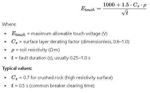
1. Allowable Touch Voltage (Etouch)
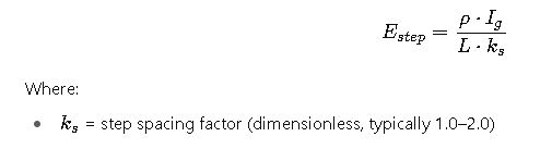
2. Allowable Step Voltage (Estep)
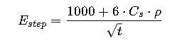
Where variables are as defined above.
3. Grid Resistance (Rg)
For a square grid with uniform soil resistivity:
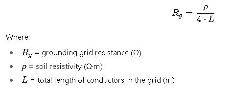
Note: This is an approximation. IEEE 80 recommends more accurate methods for irregular shapes.
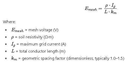
4. Mesh Voltage (Emesh)
5. Step Voltage (IEEE 80)
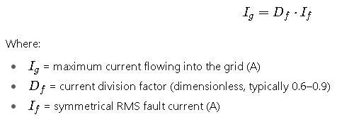
6. Maximum Grid Current (Ig)
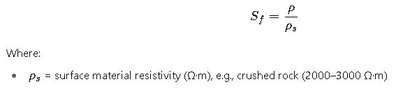
7. Reduction Factor (Sf)
The reduction factor accounts for surface material resistivity:
Practical Considerations in Substation Grounding Grid Design
While the IEEE 80 standard provides the theoretical framework, grounding design in substations requires careful consideration of field conditions, equipment constraints, and safety requirements. Below are some of the most critical factors:
Soil Resistivity Measurement
Soil resistivity is the single most influential factor in grounding design. In practice:
- Engineers use the Wenner four-pin method or the Schlumberger method to measure resistivity at various depths.
- Resistivity can vary significantly across seasons (wet vs. dry periods). Designers usually take the worst-case scenario (highest resistivity).
- In regions with layered soil, a two-layer or multilayer soil model must be applied rather than a simple uniform resistivity assumption.
Grid Geometry
- A square or rectangular grid is commonly used for substations.
- Typical conductor spacing ranges from 3 m to 7 m, depending on soil resistivity and available area.
- Additional ground rods are installed around the perimeter and at high-current equipment locations (e.g., transformer neutrals, circuit breakers).
- Grid depth is usually 0.5 m to 1 m below the surface to reduce corrosion and mechanical damage risk.
Surface Material
Covering the substation with crushed rock or gravel provides a high-resistivity surface layer, which reduces step and touch voltages. This simple, low-cost measure can drastically improve safety.
Conductor Material
- Copper is widely used due to its low resistivity and durability.
- Copper-clad steel may be considered for cost savings.
- The conductor cross-sectional area must withstand thermal and mechanical stresses during fault conditions.
Real-World Case Study 1 – 115 kV Substation in Clay Soil
Project Context:
A new 115 kV substation is to be constructed in a semi-urban area. Soil investigation revealed a uniform resistivity of 100 Ω·m. The maximum fault current at the substation bus is 40 kA with a clearing time of 0.5 s.
Design Approach:
- Soil Data Analysis: The soil resistivity of 100 Ω·m is moderate, suitable for direct grounding grid installation.
- Grid Layout: Engineers selected a rectangular grid of 60 m × 60 m with conductors spaced at 6 m intervals. The total buried conductor length is about 600 m.
- Current Distribution: Based on system studies, about 70% of the fault current (28 kA) is expected to enter the grid.
- Safety Criteria:
- Allowable touch voltage for a 70 kg person at 0.5 s is ~370 V (from IEEE 80 tables).
- Allowable step voltage is ~1040 V.
- Grid Resistance: With a conductor length of 600 m, the estimated grid resistance is around 0.04 Ω, ensuring a low ground potential rise.
- Surface Layer: The site will be covered with 100 mm of crushed rock with a resistivity of ~3000 Ω·m, improving the surface factor.
Results:
- Calculated touch voltages were below 300 V, within safe limits.
- Step voltages were about 800 V, also within IEEE 80 safety criteria.
- The design was considered safe and cost-effective, with no additional ground rods required.
Lessons Learned:
- In moderate resistivity soils, proper grid design with crushed rock surface layer provides sufficient safety.
- Careful spacing (6 m) balanced safety and cost.
Real-World Case Study 2 – 230 kV Substation in Rocky Terrain
Project Context:
An existing 230 kV substation in mountainous terrain required a grounding system upgrade. Soil resistivity tests revealed very high resistivity, averaging 2000 Ω·m. The maximum fault current is 50 kA, with a clearing time of 0.25 s.
Design Approach:
- Soil Data: High resistivity (2000 Ω·m) poses a challenge, as it increases grid resistance and potential rise.
- Grid Layout: A grid of 80 m × 80 m was designed with 5 m spacing. Additional ground rods (3 m deep) were installed at each grid intersection to improve grounding efficiency.
- Current Distribution: Approximately 60% of fault current (30 kA) expected to flow into the grid.
- Surface Treatment: To mitigate high step and touch voltages, the substation was covered with a 150 mm layer of crushed rock (resistivity ~4000 Ω·m).
- Engineering Check:
- Without ground rods, calculated touch voltage exceeded 700 V (unsafe).
- After adding ground rods, touch voltage was reduced to ~480 V.
- With the surface rock factor applied, effective touch voltage dropped below 350 V.
Results:
- The final design complied with IEEE 80 safety criteria.
- Ground rods significantly improved grounding effectiveness in high-resistivity soil.
Lessons Learned:
- In rocky terrain, additional electrodes (ground rods or deep wells) are often necessary.
- Surface treatment plays a decisive role in ensuring compliance with safety limits.
Engineering Recommendations Based on IEEE 80
Based on extensive industry experience and the IEEE 80 methodology, the following best practices are recommended for engineers designing grounding grids:
- Always perform soil resistivity tests before design; never rely solely on generic values.
- Use a safety margin in calculations to account for variations in soil conditions, measurement errors, and future system expansions.
- Consider layered soil models if resistivity varies significantly with depth.
- Prioritize safety over cost optimization, especially for high-voltage substations.
- Inspect grounding systems periodically, as corrosion or soil drying can increase resistance over time.
- Use computer-aided tools (such as ETAP, CYME, or specialized IEEE 80 software) for accurate modeling of irregular grids and multilayer soil.
Additional Reference Tables for Practical Design
Table 4 – Typical Grid Conductor Sizes (Copper)
| Fault Current (kA) | Clearing Time (s) | Recommended Conductor (mm²) | Equivalent AWG Size |
|---|---|---|---|
| 20 | 0.5 | 70 | 2/0 AWG |
| 30 | 0.5 | 120 | 3/0 AWG |
| 40 | 0.5 | 150 | 350 kcmil |
| 50 | 0.5 | 185 | 500 kcmil |
| 60 | 0.5 | 240 | 600 kcmil |
Table 5 – Typical Grid Spacing Recommendations
| Soil Resistivity (Ω·m) | Recommended Spacing (m) |
|---|---|
| < 50 | 7 – 10 |
| 50 – 200 | 5 – 7 |
| 200 – 1000 | 3 – 5 |
| > 1000 | 2 – 3 |