Proper generator sizing is essential in power system design, preventing overloads, inefficiencies, and excessive equipment wear. IEEE 446 and IEC 60034 provide standardized frameworks ensuring accurate generator capacity, safety, reliability, and efficiency.
Generator Sizing — Installed Load Method (IEEE / IEC)
Estimate the appropriate standby/prime generator kVA from installed load. Includes motors, diversity, starting allowance and selectable standards.
How does this method work?
Formulas used
Installed apparent power: S_total = Σ kVA (after diversity & duty where applied).
Generator recommended: Generator_kVA = max(S_total × ServiceFactor, PeakStarting_kVA).
Defaults & guidance
Common Parameters for Generator Sizing
The following parameters are fundamental in generator sizing according to IEEE and IEC methodologies:
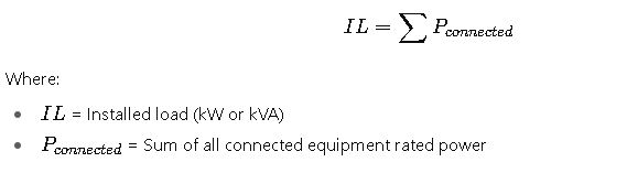
- Installed Load (kW/kVA) – The sum of connected loads before applying demand and diversity factors.
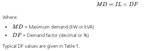
- Demand Factor (DF) – Ratio of maximum demand of a system to the total connected load.
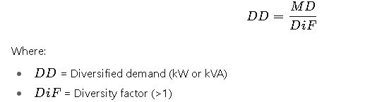
- Diversity Factor (DiF) – Accounts for the probability that not all connected loads operate simultaneously.
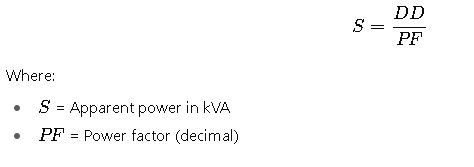
- Power Factor (PF) – Ratio of real power (kW) to apparent power (kVA).
- Starting Current Multipliers – Important for motor loads, typically 4x–7x rated current.
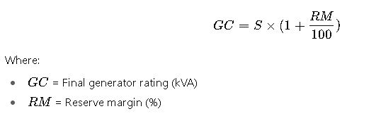
- Reserve Margin (RM) – Additional percentage to accommodate future load growth and safety margin.
Extended Reference Tables for Generator Sizing
The tables below summarize typical values used in Generator Sizing Based on Installed Load according to IEEE and IEC recommendations. These values serve as benchmarks for engineers during preliminary sizing calculations.
Table 1. Typical Demand Factors (DF) by Load Type (IEEE/IEC)
| Load Category | Typical DF (%) | Notes |
|---|---|---|
| Lighting | 90–100 | Continuous load, high utilization |
| Receptacle Outlets | 60–70 | Based on usage diversity |
| HVAC (Heating, Ventilation) | 70–90 | Depends on climate zone |
| Elevators | 40–60 | Rarely all units run simultaneously |
| Office Equipment | 50–70 | Computers, printers, etc. |
| Industrial Motors | 70–85 | Consider starting current separately |
| Kitchen Equipment | 60–80 | Dishwashers, ovens, refrigerators |
| Hospitals (Critical Loads) | 90–100 | Life-supporting loads require full redundancy |
| Data Centers | 80–95 | Continuous operation, redundancy considered |
Table 2. Diversity Factors (DiF) by Application
| Application | Typical DiF Range | Explanation |
|---|---|---|
| Residential Buildings | 1.2 – 1.5 | Loads staggered across apartments |
| Commercial Buildings | 1.3 – 1.6 | Office, retail loads vary by time of day |
| Hospitals | 1.1 – 1.3 | Critical loads operate concurrently |
| Industrial Facilities | 1.4 – 1.7 | Equipment not used simultaneously |
| Data Centers | 1.0 – 1.2 | High concurrency, redundancy requirements |
Table 3. Typical Power Factors (PF) by Load Type
| Load Type | Power Factor (lagging) | Notes |
|---|---|---|
| Incandescent Lighting | 1.00 | Purely resistive |
| Fluorescent Lighting | 0.90–0.95 | With electronic ballast |
| HVAC Motors | 0.80–0.85 | Standard induction motors |
| Industrial Motors | 0.75–0.85 | Without PF correction |
| Data Center IT Equipment | 0.95–0.98 | Modern power supplies with PF correction |
| Welders | 0.65–0.75 | Highly inductive |
| Mixed Loads (Commercial) | 0.85–0.90 | Weighted average |
Table 4. Recommended Generator Reserve Margins (RM)
| Application | Recommended RM (%) | Notes |
|---|---|---|
| Residential | 10–15 | Load growth moderate |
| Commercial Buildings | 15–20 | Expansion and seasonal variability |
| Hospitals | 25–30 | Redundancy and safety-critical considerations |
| Data Centers | 20–25 | High availability requirements |
| Industrial Facilities | 15–25 | Expansion and heavy machinery startup considerations |
Core Formulas for Generator Sizing – IEEE and IEC
Generator sizing relies on step-by-step calculations derived from international standards. Below are the primary formulas.
1. Installed Load (IL)
2. Maximum Demand (MD)
3. Diversified Demand (DD)
4. Apparent Power Requirement (S)
5. Generator Capacity (GC)
6. Motor Starting Consideration
Motors require high inrush currents during startup, typically 4–7 times the rated current. IEEE and IEC recommend checking against generator transient response:
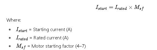
This may require step-loading strategies or soft starters to reduce initial current demand.
Real-World Application Cases for Generator Sizing
To illustrate the methodology, let us analyze two real-world scenarios with practical loads, step-by-step reasoning, and standards-based justification.
Case Study 1: Commercial Office Building (IEEE 446 / IEC 60034 Reference)
Scenario:
A 15-story office building requires a standby generator system to cover essential loads during utility outages. The building has lighting, HVAC, elevators, and office equipment.
Installed Loads:
- Lighting: 350 kW
- HVAC: 500 kW
- Elevators (6 units): 180 kW total
- Office equipment: 220 kW
- Miscellaneous receptacles: 150 kW
Step 1. Load Categorization
Lighting and HVAC are continuous and large contributors. Elevators are intermittent with lower demand probability. Office equipment and receptacles show high diversity.
Step 2. Demand Factor Application
- Lighting: ~95% → 332 kW
- HVAC: ~80% → 400 kW
- Elevators: ~50% → 90 kW
- Office equipment: ~60% → 132 kW
- Receptacles: ~65% → 98 kW
Total Demand after DF = 1052 kW
Step 3. Diversity Factor
Commercial building diversity factor ≈ 1.4.
Effective diversified load = 1052 ÷ 1.4 = 751 kW
Step 4. Power Factor & Reserve Margin
Assuming PF = 0.90, load in kVA = 751 ÷ 0.90 = 835 kVA.
Reserve margin 20% → Final Generator Rating = 835 × 1.20 ≈ 1002 kVA
Result:
Recommended generator = 1000 kVA standby diesel generator.
Technical Justification:
- Matches IEEE 446 guidelines for commercial standby power.
- IEC 60034 confirms generator thermal and transient performance at selected rating.
- Voltage dip analysis must confirm motor startup compatibility, typically managed via sequencing elevator startup or using VFDs.
Case Study 2: Industrial Manufacturing Facility (IEC 60364 / IEEE 141 Reference)
Scenario:
A medium-sized factory with large induction motors, welding machines, and continuous process equipment requires a prime-rated generator for grid-independent operation.
Installed Loads:
- Process motors: 1200 kW
- Welders: 300 kW
- Lighting & auxiliaries: 200 kW
- HVAC and support systems: 150 kW
Step 1. Demand Factor Application
- Motors: 80% → 960 kW
- Welders: 70% → 210 kW
- Lighting: 95% → 190 kW
- HVAC: 80% → 120 kW
Total Demand after DF = 1480 kW
Step 2. Diversity Factor
Industrial facility DiF ≈ 1.5.
Diversified load = 1480 ÷ 1.5 = 987 kW
Step 3. Power Factor and Apparent Power
Average PF ≈ 0.85 due to inductive loads.
kVA = 987 ÷ 0.85 = 1161 kVA
Step 4. Reserve Margin
Considering future expansion and heavy starting currents, reserve margin = 25%.
Generator Rating = 1161 × 1.25 = 1451 kVA
Result:
Recommended generator = 1500 kVA prime-rated diesel generator.
Technical Justification:
- Accounts for significant inductive loads with poor PF.
- IEEE 141 (Red Book) emphasizes correction capacitors or power factor correction equipment to avoid oversizing.
- IEC 60364 ensures protective coordination and safe thermal withstand.
Additional Technical Considerations for IEEE/IEC Compliance
1. Transient Voltage Dip
When large motors or transformers are started, generators must withstand voltage dips within acceptable IEEE/IEC limits: typically 15–20% maximum for standby systems. Excessive dips may cause sensitive equipment (e.g., IT loads, medical devices) to malfunction.
2. Frequency Stability
Generators must maintain ±5% frequency variation during sudden load changes (per IEC 60034-1). Poor frequency regulation may lead to motor overheating and malfunction of process controls.
3. Harmonic Distortion
Nonlinear loads (e.g., VFDs, UPS systems, LED lighting) generate harmonics. IEEE 519 provides harmonic limits. Sizing may need derating if THD exceeds 15% at generator terminals.
4. Load Step Sequencing
IEEE 446 recommends load sequencing to avoid starting all motors simultaneously. Automatic Transfer Switches (ATS) and load management relays stagger loads in steps to ensure generator stability.
5. Redundancy and Reliability
- Hospitals (IEC 60364-7-710, NFPA 110) require N+1 redundancy to ensure life-support continuity.
- Data centers (IEEE 3006.7) often use 2N or N+1 architectures, meaning at least one fully redundant generator is available.
6. Environmental Derating
IEC 60034 specifies derating factors based on altitude and ambient temperature.
- 1000 m elevation: derate by 1% per 100 m.
- 40°C ambient: derate by 3% per 5°C increase.
Best Practices for Generator Sizing under IEEE and IEC
- Always size in kVA, not kW – to account for power factor and reactive power.
- Apply realistic demand factors – avoid oversizing by carefully analyzing load profiles.
- Consider motor starting methods – soft starters, VFDs, and star-delta starters reduce inrush requirements.
- Future-proof design – include at least 15–25% reserve margin for expansions.
- Account for harmonics – apply IEEE 519 guidelines when nonlinear loads exceed 20% of total load.
- Perform site-specific load analysis – using data loggers to measure load profiles ensures accuracy beyond rule-of-thumb values.
- Test under full load – per IEC 60034 and IEEE 115, acceptance tests must validate generator performance with transient and steady-state load.