Electrical system insulation levels ensure equipment withstands overvoltages, lightning, and transient stresses safely. Engineers calculate BIL and Ud precisely. IEC and IEEE standards provide guidelines, common values, and correction factors, enabling reliable, compliant electrical system design.
Electrical System Insulation Level Calculator – IEC/IEEE
How is insulation level determined?
What safety factor should I use?
Formulas used
1. Common Insulation Level Values (IEC & IEEE)
The insulation level of electrical systems is determined by the Basic Insulation Level (BIL) and the Power Frequency Withstand Voltage (Ud). These values are essential for ensuring equipment can withstand transient voltages and continuous operating conditions.
1.1 IEC Standard Values
According to IEC 60071-2, insulation levels are specified for various voltage classes. The following table summarizes typical BIL and Ud values for common voltage classes:
| Voltage Class (kV) | BIL (kV peak) | Ud (kV RMS) |
|---|---|---|
| 1.2/2 | 12 | 8 |
| 3.6/6 | 36 | 24 |
| 7.2/12 | 60 | 40 |
| 12/20 | 95 | 70 |
| 17.5/30 | 125 | 95 |
| 24/40 | 170 | 125 |
| 36/63 | 250 | 170 |
| 72.5/123 | 350 | 250 |
| 145/245 | 550 | 400 |
| 245/420 | 750 | 550 |
| 420/735 | 1050 | 750 |
These values are based on sea-level conditions and standard atmospheric pressure. Adjustments may be necessary for different environmental conditions.
1.2 IEEE Standard Values
IEEE Std 1313.2 provides guidelines for insulation levels in substations. Typical BIL and Ud values are as follows:
| Voltage Class (kV) | BIL (kV peak) | Ud (kV RMS) |
|---|---|---|
| 1.2/2 | 12 | 8 |
| 4.16/7.2 | 60 | 40 |
| 13.8/24 | 110 | 80 |
| 34.5/60 | 150 | 110 |
| 69/115 | 200 | 150 |
| 138/230 | 350 | 250 |
| 230/400 | 550 | 400 |
| 345/600 | 750 | 550 |
These values are intended for equipment rated for continuous operation at the specified voltage levels.
2. Formulas for Insulation Level Calculations
2.1 Basic Insulation Level (BIL)
The BIL is determined based on the system’s maximum transient voltage. IEC 60071-2 provides a formula for calculating BIL:
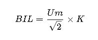
Where:
- Um= Maximum system voltage (kV RMS)
- K = Safety factor (typically 1.5 to 2.0)
2.2 Power Frequency Withstand Voltage (Ud)
Ud is the maximum voltage that equipment can withstand continuously without failure. It is calculated using the formula:
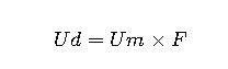
Where:
- F= Factor based on system configuration and environmental conditions (typically 1.1 to 1.2)
2.3 Altitude Correction Factor
At altitudes above sea level, the dielectric strength of air decreases, necessitating adjustments to insulation levels. The correction factor Ka is calculated as:
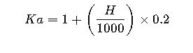
Where:
- H= Altitude above sea level (meters)
For example, at an altitude of 2000 meters:
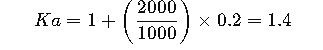
This means that insulation levels should be increased by 40% to compensate for the reduced dielectric strength at this altitude.
3. Real-World Application Examples
3.1 Medium-Voltage Distribution System
Scenario: A utility company is designing a 34.5 kV distribution system in a coastal region at sea level.
Calculation:
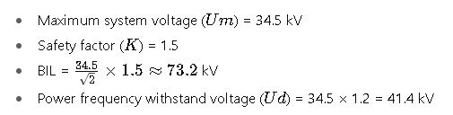
Outcome: The equipment selected must have a BIL of at least 73.2 kV and a Ud of 41.4 kV to ensure reliable operation.
3.2 High-Voltage Substation at High Altitude
Scenario: Designing a 138 kV substation at an elevation of 2500 meters.
Calculation:
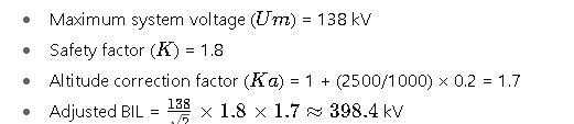
Outcome: The substation equipment must be rated for a BIL of at least 398.4 kV to withstand potential lightning strikes and ensure operational safety.
4. Additional Considerations
- Equipment Selection: Always choose equipment with insulation levels that meet or exceed the calculated BIL and Ud values.
- Environmental Factors: Consider factors such as humidity, pollution, and temperature, which can affect insulation performance.
- Standards Compliance: Ensure all designs comply with relevant IEC and IEEE standards to maintain safety and reliability.
5. References
- IEC 60071-2: Insulation coordination – Part 2: Application guide
- IEEE Std 1313.2: IEEE Guide for the Application of Insulation Coordination
- NEPSI Altitude Correction Calculator: https://nepsi.com/resources/calculators/altitude-correction.htm
- Electrical4U: Basic Insulation Level Definition and Calculation: https://www.electrical4u.com/basic-insulation-level-definition-table-and-calculation/
- Electrical Engineering Portal: BIL Definition: https://electrical-engineering-portal.com/definition-basic-insulation-level-bil