Geospatial data supports mapping, navigation, surveying, and engineering. Coordinates numerically represent geographic positions across Earth. Different coordinate systems exist, requiring conversion. A converter ensures accuracy across cartography, geodesy, engineering, aviation, and GNSS.
Coordinates Converter — Decimal Degrees ⇄ DMS ⇄ DM
Convert between decimal degrees, degrees-minutes-seconds (DMS), and degrees + decimal minutes (DM). Enter latitude and longitude in many common formats and get instant, accurate results ready for GeoJSON, CSV, or Google Maps.
What formats does this converter support?
How to input DMS values?
Formulas used
Convert DM → DD: DD = sign · (degrees + minutes/60).
Where sign is + for N/E or − for S/W (or numeric negative).
Why is normalization important?
Common Coordinate Formats
Coordinates can be represented in different formats depending on context, measurement system, and application. Below is a detailed reference table of the most common formats.
Table 1. Common Coordinate Systems and Examples
| Coordinate System | Format | Example | Notes |
|---|---|---|---|
| Decimal Degrees (DD) | ±DD.DDDDD° | 40.71278° N, -74.00597° W | Common in GPS, Google Maps |
| Degrees Decimal Minutes (DDM) | ±DD° MM.MMM′ | 40° 42.767′ N, 74° 00.358′ W | Used in marine navigation |
| Degrees Minutes Seconds (DMS) | ±DD° MM′ SS.S″ | 40° 42′ 46.6″ N, 74° 00′ 21.5″ W | Traditional surveying |
| Universal Transverse Mercator (UTM) | Zone + Easting + Northing | Zone 18T 585000mE 4511000mN | Based on metric units |
| Military Grid Reference System (MGRS) | Zone + Grid Square + Coordinates | 18T WL 85000 11000 | NATO/US military |
| Geocentric (ECEF XYZ) | X, Y, Z in meters | X = 1330554.6, Y = -4654952.3, Z = 4138301.7 | Used in GNSS/space geodesy |
Mathematical Formulas for Coordinate Conversion
Precise coordinate transformation requires well-defined formulas. Below are the key equations, with variables explained in detail.
1. Degrees Minutes Seconds (DMS) to Decimal Degrees (DD)
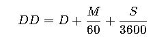
- D = Degrees (integer, may be negative for W/S)
- M = Minutes (0–59)
- S = Seconds (0–59.999)
- DD = Decimal Degrees
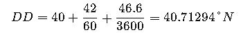
Example:
Convert 40° 42′ 46.6″ N to DD. DD
2. Decimal Degrees (DD) to Degrees Minutes Seconds (DMS)
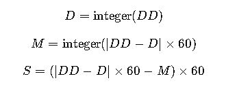
- Useful in traditional surveying and nautical charts.
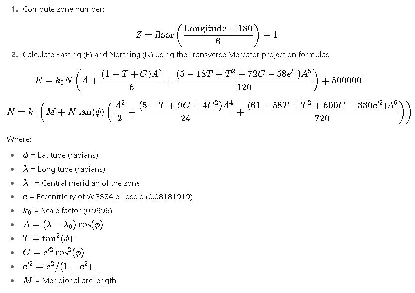
3. Geographic (Lat/Lon) to UTM
The Universal Transverse Mercator system divides the Earth into 60 longitudinal zones. Conversion involves several steps:
4. UTM to Geographic Coordinates
The inverse formulas compute latitude and longitude back from UTM coordinates. While more complex, modern converters implement these equations using iterative methods (e.g., Bowring’s formula).
5. Earth-Centered Earth-Fixed (ECEF XYZ) to Geographic (Lat/Lon/Alt)
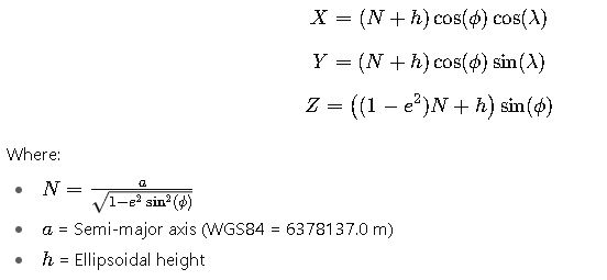
These are critical for GNSS and satellite-based positioning systems.
Extended Conversion Reference Table
Table 2. Conversion Between Coordinate Formats
| From → To | Formula / Method | Example |
|---|---|---|
| DMS → DD | DD=D+M/60+S/3600DD = D + M/60 + S/3600DD=D+M/60+S/3600 | 40°42′46.6″ → 40.71294° |
| DD → DMS | Integer decomposition | -74.00597° → 74°00′21.5″ |
| DD → UTM | Transverse Mercator projection | -74.006°, 40.713° → Zone 18T 585000mE 4511000mN |
| UTM → DD | Inverse Transverse Mercator | Zone 18T 585000, 4511000 → 40.713°, -74.006° |
| Geographic → ECEF | XYZ equations | 40.713°, -74.006°, h=10m → (1330554, -4654952, 4138302) |
| ECEF → Geographic | Iterative inverse | (1330554, -4654952, 4138302) → 40.713°, -74.006° |
Practical Applications of Coordinates Converters
While the mathematics behind coordinate systems is essential, the real value lies in their practical applications. Below are detailed examples of how coordinates conversion is used in different industries.
Case Study 1: Urban Planning and Civil Engineering
A city’s urban development office receives land survey data in UTM coordinates, while their GIS platform requires input in decimal degrees (DD) for compatibility with Google Maps and satellite imagery. The conversion ensures seamless integration between datasets.
Scenario:
- A surveyor provides parcel boundaries in UTM Zone 17N:
- Easting: 450,000 mE
- Northing: 5,000,000 mN
- The engineering team needs latitude/longitude to align the data with municipal planning maps.
Steps:
- Use a coordinates converter tool or GIS software (such as QGIS or ArcGIS) to transform UTM into DD.
- The resulting coordinates:
- Latitude ≈ 45.14° N
- Longitude ≈ -83.11° W
Impact:
- Engineers can overlay infrastructure data (roads, water lines, zoning) on Google Maps.
- Consistency between surveying data and public mapping tools avoids costly misalignments.
Why it matters:
A mismatch of even a few meters can lead to errors in road alignment, misplaced utilities, or property boundary disputes. Coordinate conversion guarantees accuracy across different data sources.
Case Study 2: Aviation and Air Traffic Management
Airports and aircraft rely on precise coordinate formats for navigation and communication. However, aviation maps often use Degrees, Minutes, Seconds (DMS), while GPS systems typically output Decimal Degrees (DD).
Scenario:
- A pilot is given a waypoint in flight plan format:
- 40°42′46″ N, 74°00′21″ W (DMS)
- The onboard GPS only accepts decimal degrees.
Conversion Result:
- Latitude: 40.7128°
- Longitude: -74.0058°
Impact:
- The aircraft’s navigation system can accurately direct the pilot.
- Ensures synchronization between air traffic control (ATC), which may use different coordinate representations, and aircraft avionics.
Why it matters:
Precision in aviation is a matter of safety. A 0.01° error equals about 1.11 km at the equator—enough to deviate an aircraft from its intended route. Reliable converters eliminate this risk.
Broader Applications of Coordinate Conversion
Beyond the two detailed examples, coordinate converters are critical in many other industries:
- Maritime Navigation: Ships use DDM (Degrees Decimal Minutes) with nautical charts, but GPS often outputs DD. Accurate conversion is essential for safe sea routes.
- Military Operations: NATO relies on MGRS, while international partners may use UTM or DD. Converters ensure compatibility between systems in joint operations.
- Space Missions: Satellite tracking uses ECEF (Earth-Centered Earth-Fixed) coordinates, which must be translated into geographic lat/lon for ground control interpretation.
- Environmental Monitoring: Datasets from satellites (ECEF) and field sensors (DD or UTM) need consistent formats for climate and biodiversity analysis.
- Telecommunications: Cellular networks use geographic coordinates for antenna placement, while design simulations often require Cartesian (X, Y, Z).
Variables and Their Common Ranges (Simplified)
Instead of focusing heavily on formulas, let’s consider the typical ranges and values for coordinate-related variables:
| Variable | Range / Common Values | Usage |
|---|---|---|
| Latitude (φ) | -90° (South Pole) to +90° (North Pole) | Defines north-south position |
| Longitude (λ) | -180° (W) to +180° (E) | Defines east-west position |
| UTM Zone | 1–60 | Each zone covers 6° longitude |
| UTM Easting | 166,000 m – 834,000 m | Centered around zone meridian |
| UTM Northing | 0–10,000,000 m | From equator to poles |
| Altitude (h) | -500 m (Dead Sea) to >8,800 m (Everest) | Height above sea level |
| ECEF X, Y, Z | -6,378 km to +6,378 km | Cartesian radius of Earth |
These ranges help validate coordinates when working with converters. For instance, a latitude of 125° would immediately indicate an input error, since the valid range is only ±90°.
Best Practices for Coordinate Conversion
When using coordinates converters in professional contexts, certain practices improve reliability:
- Confirm the Datum:
Always check whether the system is using WGS84, NAD83, or another ellipsoid. A mismatch can create position errors of 1–200 meters. - Check Zone Assignments:
UTM zones differ; using the wrong one may place a point thousands of kilometers away. - Avoid Rounding Too Early:
Keep at least 5–6 decimal places in decimal degrees for precision. - Cross-Verify with Multiple Tools:
Use GIS software, online converters, and field GPS devices to ensure consistency. - Document the Conversion Method:
In engineering and legal contexts, always record which formulas, software, and datum were used.