Selecting the correct contactor for motor applications ensures operational safety, efficiency, reliability, and optimal system performance.This guide explores IEC-compliant contactor selection, providing formulas, tables, examples, and practical technical considerations.
Contactor Selection for Motors Calculator – IEC
Which current is used for contactor selection?
Formulas used
Contactor rating = I_motor * Start Factor (1.0 for DOL, 1.6 for Star-Delta, 1.2 for Soft Starter)
IEC Contactor Selection Tables
The International Electrotechnical Commission (IEC) provides standardized guidelines for selecting contactors based on motor ratings and application types. Below are comprehensive tables that outline common motor sizes, their corresponding full-load currents (FLA), and recommended contactor sizes according to IEC standards.
Table 1: Full-Load Current (FLA) for Three-Phase Motors
| Motor Power (kW) | Voltage (V) | FLA (A) | Utilization Category | Recommended Contactor Size (A) |
|---|---|---|---|---|
| 1.1 | 400 | 2.4 | AC-3 | 4 |
| 2.2 | 400 | 4.8 | AC-3 | 6 |
| 3.0 | 400 | 6.5 | AC-3 | 8 |
| 5.5 | 400 | 12.0 | AC-3 | 16 |
| 7.5 | 400 | 15.0 | AC-3 | 20 |
| 11 | 400 | 22.0 | AC-3 | 25 |
| 15 | 400 | 30.0 | AC-3 | 32 |
| 18.5 | 400 | 37.0 | AC-3 | 40 |
| 22 | 400 | 44.0 | AC-3 | 50 |
| 30 | 400 | 60.0 | AC-3 | 63 |
Note: FLA values are approximate and may vary based on motor efficiency and power factor.
Table 2: Contactor Utilization Categories
| Category | Description | Application Examples |
|---|---|---|
| AC-1 | Non-inductive or slightly inductive loads | Lighting, heating |
| AC-2 | Slip-ring motors | Wound rotor motors |
| AC-3 | Squirrel-cage motors (starting and stopping) | Pumps, fans, compressors |
| AC-4 | High-frequency switching (inching, plugging) | Conveyors, hoists |
| AC-5a | Switching of electrical discharge lamps | Fluorescent lighting circuits |
| AC-5b | Switching of incandescent lamps | Incandescent lighting circuits |
| AC-6a | Switching of transformers | Transformer circuits |
| AC-6b | Switching of capacitor banks | Power factor correction circuits |
| AC-7a | Slightly inductive loads in household applications | Small appliances |
| AC-7b | Motor loads in household applications | Household motors |
| AC-8a | Hermetic refrigerant compressor motors (manual reset) | Refrigeration units |
| AC-8b | Hermetic refrigerant compressor motors (auto reset) | Refrigeration units |
| AC-11 | Auxiliary control circuits | Control circuits |
| AC-12 | Control of resistive and solid-state loads with opto-coupler isolation | Control circuits |
| AC-13 | Control of resistive loads and solid-state with T/C isolation | Control circuits |
| AC-14 | Control of small electromagnetic loads (<72VA) | Small relays, solenoids |
| AC-15 | Control of small electromagnetic loads (>72VA) | Small relays, solenoids |
Formulas for Contactor Selection
Accurate contactor selection requires precise calculations of motor parameters. Below are the key formulas used in IEC-compliant contactor sizing.
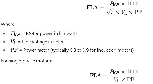
1. Full-Load Current (FLA)
For three-phase motors:
2. Contactor Size
The recommended contactor size is typically 1.25 to 1.5 times the FLA to account for inrush currents and ensure reliable operation.

Where the safety factor ranges from 1.25 to 1.5, depending on the application.
3. Making/Breaking Capacity
The making/breaking capacity indicates the maximum current the contactor can handle during switching operations. It is calculated as:

The making cap multiplier varies based on the utilization category (e.g., AC-3, AC-4).
Real-World Application Examples
Example 1: Pump Motor Selection
Motor Specifications:
- Power: 7.5 kW
- Voltage: 400 V
- Power Factor: 0.85
- Utilization Category: AC-3
Calculations:
- FLA = (7.5 × 1000) / (1.732 × 400 × 0.85) ≈ 12.3 A
- Recommended Contactor Size = 12.3 A × 1.25 ≈ 15.4 A
Conclusion:
A contactor rated at 16 A AC-3 would be suitable for this application, providing adequate capacity for motor starting and stopping operations.
Example 2: HVAC Fan Motor Selection
Motor Specifications:
- Power: 5.5 kW
- Voltage: 400 V
- Power Factor: 0.9
- Utilization Category: AC-1
Calculations:
- FLA = (5.5 × 1000) / (1.732 × 400 × 0.9) ≈ 8.8 A
- Recommended Contactor Size = 8.8 A × 1.25 ≈ 11 A
Conclusion:
A contactor rated at 12 A AC-1 would be appropriate for this application, ensuring reliable operation for resistive loads.
Advanced Considerations in IEC Contactor Selection for Motors
1. Coordination with Overload Relays
IEC standards emphasize the importance of coordinating contactors with overload relays to ensure protection against motor faults. This coordination is classified into two types:
- Type 1 Coordination: In the event of a fault, the overload relay operates to protect the motor, but the contactor may be damaged.
- Type 2 Coordination: Both the overload relay and the contactor operate to protect the motor, ensuring no damage to the contactor.
Proper coordination ensures the longevity and reliability of the motor control circuit.
2. Short-Circuit Protection
IEC 60947-4-1 specifies that contactors must be coordinated with short-circuit protective devices, such as fuses or circuit breakers. The maximum permissible short-circuit current rating of the contactor must match or exceed the prospective short-circuit current at the point of installation. This coordination prevents damage to the contactor and ensures safe operation during fault conditions.
3. Ambient Temperature and Derating
The performance of contactors can be affected by ambient temperature. IEC standards provide guidelines for derating contactors when operating temperatures exceed standard conditions (e.g., 40°C). For every 10°C rise above the standard temperature, the rated current of the contactor should be reduced by approximately 10%. This derating ensures the contactor operates within safe thermal limits.
4. Altitude Considerations
At higher altitudes, the dielectric strength of air decreases, which can affect the performance of contactors. IEC standards recommend derating contactors for installations at altitudes above 2,000 meters. The recommended derating factor is 1% per 100 meters above 2,000 meters. This adjustment ensures reliable operation in elevated locations.
5. Motor Starting Methods
The method of motor starting influences the selection of contactors:
- Direct-On-Line (DOL): For small motors, where the contactor directly connects the motor to the power supply.
- Star-Delta Starting: For larger motors, reducing inrush current by initially connecting the motor in a star configuration and then switching to delta.
- Autotransformer Starting: Uses an autotransformer to reduce voltage and current during startup.
Each starting method requires specific contactor ratings and configurations to ensure safe and efficient operation.
Practical Application Examples
Example 1: Pump Motor Installation
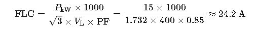
Scenario: A 15 kW, 400 V, three-phase pump motor is to be installed in a chemical processing plant.
- Full Load Current (FLC): Using the formula:
- Contactor Size: Applying a safety factor of 1.25:
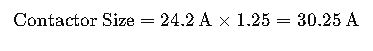
Therefore, a 32 A contactor is selected.
- Utilization Category: For squirrel-cage motors, the appropriate category is AC-3.
- Making Capacity: The making capacity for AC-3 is 10 times the FLC:
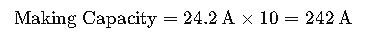
Thus, the contactor must handle a making capacity of at least 242 A.
Conclusion: A 32 A AC-3 contactor with a making capacity of at least 242 A is suitable for this application.
Example 2: HVAC Fan Motor Upgrade
Scenario: Upgrading an existing HVAC system with a 7.5 kW, 400 V, three-phase fan motor.
- Full Load Current (FLC): Using the formula:
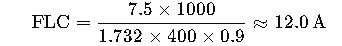
- Contactor Size: Applying a safety factor of 1.25:

Therefore, a 16 A contactor is selected.
- Utilization Category: For resistive loads, the appropriate category is AC-1.
- Making Capacity: The making capacity for AC-1 is 1.5 times the FLC:

Thus, the contactor must handle a making capacity of at least 18 A.
Conclusion: A 16 A AC-1 contactor with a making capacity of at least 18 A is suitable for this application.
Additional Resources
For further information and tools related to IEC contactor selection:
- Contactor Size Calculator: An online tool to calculate the appropriate contactor size based on motor power, voltage, phase, and application type.
- IEC Motor Data Calculator: A downloadable calculator that provides typical Full Load Amps (FLA), wire size, fuse rating, and recommended contactor and overload relay sizes.
- Schneider Electric Motor Data Calculator: A comprehensive tool for selecting motor protection and control components, including contactors and overload relays.