This conduit size calculator simplifies NEC compliance and conduit fill calculations for electrical professionals worldwide.
It integrates trade sizes, fill percentages, and cable types to ensure safe, code-compliant installations globally.
Conduit Size Calculator — NEC Fill Check and Required Diameter
Regulatory basis and essential NEC rules for conduit fill
The National Electrical Code (NEC) defines conduit fill limits, conductor counting, and methods required to determine minimum conduit size. Key NEC provisions include:
- NEC Chapter 3 (Wiring Methods) and Article 300 for raceways and conductors.
- NEC Chapter 9, Tables 1–8, which provide cross-sectional areas of conductors, raceway internal areas, and fill percentages.
- NEC rules for conductor ampacity derating (e.g., 310.15(B)(3)(a)) when more than three current-carrying conductors occupy a raceway.
Always cross-check the local enforcement edition of the NEC, and consult product manufacturer dimensions for precise insulated conductor diameters.
Core calculation logic for an easy NEC conduit size tool
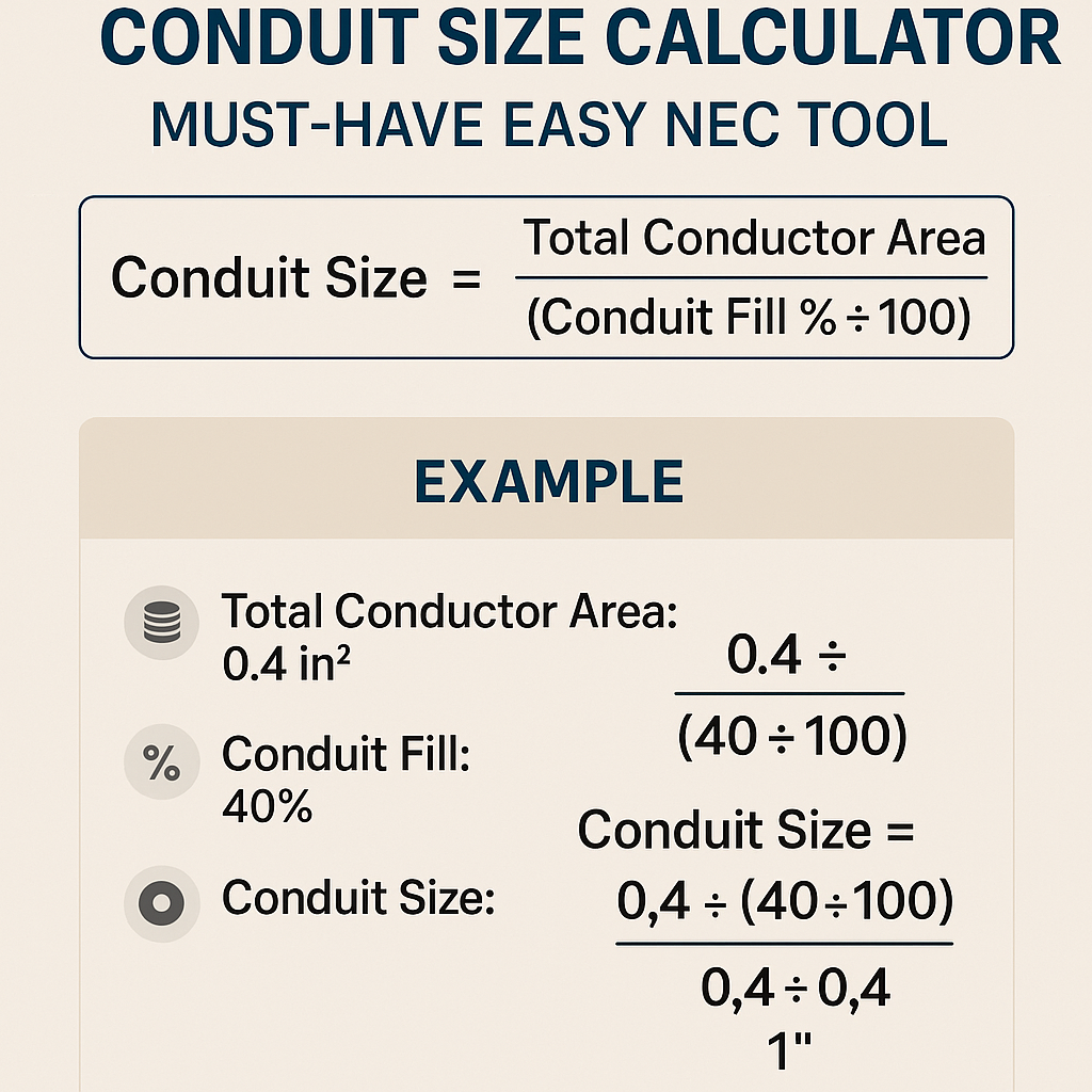
At its core, a conduit size calculator performs three operations:
- Obtain internal cross-sectional area of the candidate conduit (A_conduit).
- Determine the insulated conductor cross-sectional area (A_conductor) for each conductor to be placed in that conduit.
- Calculate if the sum of conductor areas fits within allowed conduit fill percentage per NEC (one conductor = 53%, two conductors = 31%, three or more = 40%).
Formula set (HTML format only)
Variables and typical values
- D — insulated conductor outer diameter (inches). Typical values depend on conductor type (THHN, XHHW-2, etc.). Example THHN diameters used in examples below are typical vendor nominal sizes.
- Area_conductor — cross-sectional area of each insulated conductor, in square inches (calculated from D).
- A_conduit — internal cross-sectional area of the conduit (square inches) from NEC Chapter 9, Table 4 or manufacturer data.
- FillFraction(n) — permitted fill per NEC:
- n = 1 ⇒ 0.53 (53%)
- n = 2 ⇒ 0.31 (31%)
- n ≥ 3 ⇒ 0.40 (40%)
- A_total — sum of all conductor areas; must be ≤ A_allowed.
Reference conduit internal areas and usable fill (EMT examples)
The table below uses standard EMT internal areas from NEC Chapter 9 Table 4 as reference values. Values are widely used for quick design calculations. Always verify with the edition of NEC adopted by the Authority Having Jurisdiction (AHJ).
| EMT Trade Size | Internal Area (sq in) | 53% Allowed (one conductor) | 40% Allowed (3+ conductors) |
|---|---|---|---|
| 1/2" | 0.304 | 0.1611 | 0.1216 |
| 3/4" | 0.533 | 0.2825 | 0.2132 |
| 1" | 0.864 | 0.4579 | 0.3456 |
| 1-1/4" | 1.496 | 0.7929 | 0.5984 |
| 1-1/2" | 1.939 | 1.0287 | 0.7756 |
| 2" | 3.356 | 1.7787 | 1.3424 |
| 2-1/2" | 5.211 | 2.7618 | 2.0844 |
| 3" | 6.985 | 3.7021 | 2.7940 |
| 3-1/2" | 9.478 | 5.0233 | 3.7912 |
| 4" | 12.742 | 6.7533 | 5.0968 |
Common insulated conductor diameters and calculated areas (typical THHN)
Manufacturer dimensions vary. The following are typical nominal insulated conductor outer diameters (THHN) used for planning and calculation. Cross-sectional areas are computed with Area = π × (D/2)^2 and stated in square inches.
| AWG / Size | Nominal D (in) | Area (sq in) |
|---|---|---|
| 14 AWG | 0.144 | 0.0163 |
| 12 AWG | 0.162 | 0.0206 |
| 10 AWG | 0.189 | 0.0281 |
| 8 AWG | 0.230 | 0.0416 |
| 6 AWG | 0.289 | 0.0656 |
| 4 AWG | 0.346 | 0.0940 |
| 2 AWG | 0.409 | 0.1314 |
| 1 AWG | 0.459 | 0.1655 |
| 1/0 | 0.524 | 0.2155 |
| 2/0 | 0.589 | 0.2724 |
| 3/0 | 0.662 | 0.3445 |
| 4/0 | 0.730 | 0.4186 |
Step-by-step design procedure an easy NEC tool should implement
- Input conductor types, sizes, and count. For each conductor, use manufacturer insulation diameter (D) or a validated database of insulated diameters.
- Calculate each conductor area using Area_conductor = π × (D / 2) × (D / 2).
- Sum areas to get A_total.
- Select candidate conduit trade sizes and read internal area (A_conduit) from standardized tables (NEC Chapter 9 Table 4 or vendor catalog).
- Find FillFraction based on conductor count and determine A_allowed = FillFraction × A_conduit.
- Compare: A_total ≤ A_allowed → conduit acceptable. Otherwise increase conduit size or change conductor configuration (e.g., split runs).
- If more than three current-carrying conductors, apply conductor ampacity derating per NEC 310.15(B)(3)(a) and verify derated ampacity meets load requirements.
Real-world example 1 — Small branch circuit: three 12 AWG THHN in 1/2" EMT
Problem statement: Determine whether three 12 AWG THHN insulated conductors will fit into 1/2" EMT conduit, and if not, find minimum EMT trade size.
Given
- Three conductors, each 12 AWG THHN.
- Nominal insulated conductor diameter D = 0.162 inches (typical vendor value).
- EMT internal area for 1/2" = 0.304 sq in (NEC Table 4).
- For three conductors, use 40% fill (FillFraction = 0.40).
Calculations
Result and commentary
Because A_total (0.06186) ≤ A_allowed (0.1216), three 12 AWG THHN conductors fit easily in 1/2" EMT. There remains headroom for additional insulated conductors up to the 40% fill limit (approximate maximum identical 12 AWG count = floor(0.1216 / 0.02062) = 5 conductors).
Note: If you must include an equipment grounding conductor, verify whether to include it in the area calculation per the AHJ and applicable NEC guidance (equipment grounding conductor may be counted as one conductor for fill purposes in most cases; consult latest NEC text and interpretations).
Real-world example 2 — Feeder with large conductors: four 4/0 THHN in EMT
Problem statement: Determine the minimum EMT trade size to contain four copper 4/0 THHN conductors and comment on ampacity derating.
Given
- Four insulated 4/0 THHN copper conductors.
- Nominal insulated conductor diameter D = 0.730 inches (typical vendor data).
- EMT internal areas per Table (1-1/2, 2, 2-1/2, etc.).
- Since there are four conductors (≥3), use FillFraction = 0.40.
Calculations
Step 3: Required conduit internal area to satisfy 40% fill: A_needed = A_total / 0.40 = 1.6744 / 0.40 = 4.186 sq in
Step 4: Compare candidate EMT sizes: - 2" EMT internal area = 3.356 sq in (insufficient) - 2-1/2" EMT internal area = 5.211 sq in (sufficient)
Result and commentary
Minimum EMT trade size to accommodate four 4/0 THHN insulated conductors is 2-1/2" EMT (because 2" is insufficient). The 2-1/2" EMT provides A_allowed (40%) = 5.211 × 0.40 = 2.0844 sq in which exceeds A_total 1.6744 sq in.
Ampacity derating: Four current-carrying conductors implies more than three conductors in the same conduit, therefore apply NEC 310.15(B)(3)(a) conductor grouping derating factors to the ampacity (for examples, 4–6 conductors ⇒ 80% of the column ampacity; confirm the exact factor in the NEC edition you use). Verify derated ampacity against required load and adjust conductor size if necessary.
Additional considerations for a robust easy NEC conduit tool
- Database of insulated conductor outer diameters by type (THHN, XHHW-2, USE-2, MC cable dimensions) and by manufacturer.
- Raceway internal area tables for multiple raceway types (EMT, RMC, IMC, Schedule 40 & 80 PVC) with user-selectable units (in² / mm²).
- Automatic selection of the correct fill fraction based on conductor count and cable type (individual conductors vs cable assemblies).
- Ampacity derating module that applies NEC multipliers when more than three current-carrying conductors are present, and temperature correction factors for ambient temperature variations.
- Back-check for mechanical pulling stresses for long runs and for need for intermediate pull boxes or larger trade size to keep fill and pullability reasonable.
- Option to include equipment grounding conductors per local AHJ rule interpretations and NEC guidance.
Special cases, edge rules and caveats
- NEC differentiates between single insulated conductors and cable assemblies; cable assemblies typically are treated as a single conductor for fill calculations (check relevant NEC paragraphs for exceptions).
- For one conductor in a raceway, allowed fill is 53%. For two conductors, 31%. For three or more, 40%. These rules apply to individual insulated conductors; different rules may apply for conductors installed within a cable assembly.
- Always use manufacturer outer-diameter drawings for final designs; nominal values and rounded table values are acceptable for preliminary sizing but not for final stamped drawings when tolerances are tight.
- Conduit fill calculations are geometric and conservative; practical cable pulling and long-term maintenance considerations sometimes drive choices to a larger conduit than the minimum strictly required by fill rules.
Algorithm outline for a programmatic conduit size calculator
- Accept input: conductor list (type, AWG, quantity), include ground? ambient temperature, number of current-carrying conductors.
- Retrieve or compute insulated diameter for each conductor.
- Compute each conductor area and sum to A_total.
- Iterate through conduit types and trade sizes; for each:
- Pull A_conduit from table.
- Select FillFraction based on conductor count or assembly rule.
- Test if A_total ≤ FillFraction × A_conduit. If yes, mark candidate as acceptable.
- Return smallest trade size that meets fill rule and present alternatives with margins and mechanical advice (ease of pulling, derating warnings).
Practical UX features for the “Must Have Easy NEC Tool”
- Auto-suggest conduit sizes with a “safety margin” setting (e.g., 10–25% spare capacity recommended by installers for easier pulling).
- Interactive conductor bank builder (drag/drop counts by AWG or import BOM).
- Exportable calculation reports that cite NEC sections and show step-by-step math for AHJ plan review.
- Localization: switch between NEC and IEC rules for international projects (IEC typically uses metric cross-sections and different installation rules; tool should adapt equations and standards accordingly).
Standards, normative references and further reading
- NFPA 70 — National Electrical Code (NEC). See the NFPA resource page: https://www.nfpa.org/NEC
- NEC Chapter 9 — Tables 1–8 (raceway and conductor cross-sectional areas, conduit fill percentages). Refer to the edition adopted by the AHJ.
- IEC 60364 — Electrical installations of buildings (for international design practice) — https://www.iso.org/ — consult the IEC/ISO catalog for specifics.
- NEMA and manufacturer conduit tables and dimension data (NEMA publishes conduit and fitting standards) — https://www.nema.org/
- UL and manufacturer data sheets for insulated conductor outer diameters (THHN/XHHW-2). Manufacturer catalogs (e.g., Southwire, Prysmian) provide actual insulation diameters.
- OSHA construction electrical safety resources and industry best practices — https://www.osha.gov/
Best practices and field tips
- Always use manufacturer insulation diameter for final fill computations; vendor tolerances affect results significantly for tight fits.
- Prefer the next larger conduit size if the computed fill margin is less than 10% to facilitate pulling, adding future conductors, or accommodating thicker insulation variants.
- Document assumptions (insulation type, diameter used, NEC edition) in the calculation report for plan reviewers and inspectors.
- For mixed conductor sizes, compute each conductor area individually rather than using averaged diameters.
Summary of essential formulas and quick references
Total area and fill test: ΣArea_conductors ≤ FillFraction × A_conduit
Max identical conductors: floor( (FillFraction × A_conduit) / Area_conductor )
Final notes on compliance and validation
A conduit size calculator streamlined for NEC compliance must combine accurate geometric calculations with up-to-date normative tables and conductor dimension databases. Outputs should always be validated against the edition of the Code enforced by the project AHJ and manufacturer datasheets. For critical feeders, cross-check mechanical pull calculations, conductor ampacity derating, and thermal considerations as part of the same design workflow.
For authoritative reading, consult the cited NFPA and NEMA resources, and use manufacturer datasheets for conductor diameters and conduit internal area data for final design verification.