Accurate conduit and cable tray fill calculation prevents overheating, ensures compliance, and optimizes installation costs.
This article describes best calculators, formulas, examples, standards, and practical workflows for engineers field applications.
Conduit and Cable Tray Fill Calculator — Best Tool for Engineering Checks
Why precise fill calculation is essential for electrical infrastructure
Conduit and cable tray fill affect thermal performance, conductor ampacity, mechanical pull tensions, and maintenance access. Mis-sizing causes derating, overheating, voltage drop, excessive installation labor, and possible code noncompliance.
Modern projects require fast, auditable calculations that incorporate manufacturer geometry, multi-standard rules, and project-specific constraints for reproducible decisions.
Regulatory context and standards to consider
Designers must reconcile local code with international practice. The most commonly referenced documents are:
- NFPA 70 (NEC) — conduit fill rules, Chapter 9 tables, and cable tray guidance (Article 392).
- IEC 61537 — cable tray systems and accessories (mechanical design and mechanical compatibility).
- Manufacturer datasheets — precise outer cable/conductor diameters and recommended bundling guidelines.
- Local regulations and utility specifications that may be stricter than international codes.
Authoritative links:
- NFPA (National Fire Protection Association) — NFPA 70 (NEC) reference and code purchase.
- IEC (International Electrotechnical Commission) — standards database including IEC 61537.
- NEMA — tray and enclosure guidance.
- ISO — quality and management system standards relevant to design workflows.
Key principles and accepted fill rules
Most jurisdictions apply the following practical rules (NEC-derived):
- One conductor in a conduit: maximum fill = 53% of conduit internal area.
- Two conductors: maximum fill = 31% of conduit internal area.
- Three or more conductors: maximum fill = 40% of conduit internal area.
- Cable tray: manufacturer and code-based percentages vary; designers often use 40% for initial ventilation allowance and confirm with local code or manufacturer.
These percentages are used by calculators to convert conductor/cable cross-sectional area sums into percent fill.
Fundamental formulas (with variable definitions and typical values)
Conductor cross-sectional area (insulated cable or round conductor)
Use the circular area formula for round insulated conductors or approximate for near-round cable cross-sections:
Where:
- A_c = conductor (or insulated conductor) cross-sectional area (mm² or in²)
- d = outer conductor insulating diameter (mm or inches)
- π = 3.14159265358979
Typical values (examples):
- #12 AWG THHN: d ≈ 2.6 mm → A_c = π × (2.6 / 2)^2 ≈ 5.31 mm² (insulation included).
- #8 AWG THHN: d ≈ 4.2 mm → A_c ≈ π × (2.1)^2 ≈ 13.85 mm².
Conduit internal cross-sectional area
For circular conduit internal diameter D:
Where:
- A_t = conduit internal cross-sectional area (same units as A_c)
- D = internal diameter of conduit (mm or inches), obtained from manufacturer or trade tables
Typical D values must come from conduit product tables; calculators include standard library values.
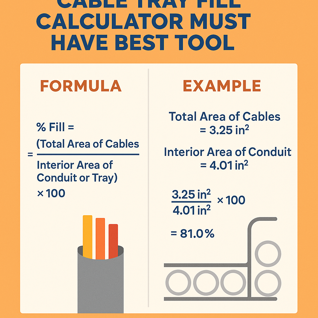
Total fill percentage
Compute total percentage fill as:
Where:
- ΣA_c = sum of all individual conductor/cable cross-sectional areas within the conduit or tray
- A_t = area available for conductors (for conduit, the internal area; for trays, tray cross section or width × usable height)
Then compare Fill % with allowable percent based on rule set (e.g., 40% for three or more conductors).
Recommended fields captured by an ideal conduit and cable tray fill calculator
A high-quality calculator must accept both empirical data and code logic:
- Project units (metric/imperial) and automatic conversion.
- Select conductor type (THHN, XHHW, multicore power cable) with library diameters or manual entry.
- Conduit/tray selection with library of internal diameters and tray dimensions (including ladder, ventilated, solid bottom).
- Number of conductors per phase and neutral, and differentiation for grouped cables.
- Code mode toggle (NEC, IEC, manufacturer limits) to change allowable fill percentage and derating factors.
- Bundle derating calculator and ampacity adjustments linked to fill results.
- Detailed report export: inputs, calculations, normative references, and recommended corrective actions when overfilled.
Extensive reference tables with common values
| Conductor (AWG / IEC) | Nominal Conductor Area (mm²) | Typical Insulated Diameter (mm) | Calculated Insulated Area (mm²) |
|---|---|---|---|
| 14 AWG | 2.08 | 2.1 | π × (2.1 / 2)^2 ≈ 3.46 |
| 12 AWG | 3.31 | 2.6 | π × (2.6 / 2)^2 ≈ 5.31 |
| 10 AWG | 5.26 | 3.3 | π × (3.3 / 2)^2 ≈ 8.55 |
| 8 AWG | 8.37 | 4.2 | π × (4.2 / 2)^2 ≈ 13.85 |
| 6 AWG | 13.3 | 5.4 | π × (5.4 / 2)^2 ≈ 22.90 |
| 4 AWG | 21.2 | 6.8 | π × (6.8 / 2)^2 ≈ 36.32 |
| 2 AWG | 33.6 | 8.9 | π × (8.9 / 2)^2 ≈ 62.22 |
| 1/0 AWG | 53.5 | 11.0 | π × (11.0 / 2)^2 ≈ 95.03 |
| Conduit Type / Trade Size | Nominal Internal Diameter (mm) | Internal Area (mm²) | Recommended Max Fill % (NEC-based) |
|---|---|---|---|
| EMT 1/2" | 16.0 | π × (16.0 / 2)^2 ≈ 201.06 | 40% (3+ conductors) |
| EMT 3/4" | 21.2 | π × (21.2 / 2)^2 ≈ 353.06 | 40% |
| EMT 1" | 26.7 | π × (26.7 / 2)^2 ≈ 560.06 | 40% |
| Rigid 1" | 27.8 | π × (27.8 / 2)^2 ≈ 607.53 | 40% |
| Rigid 1-1/4" | 35.1 | π × (35.1 / 2)^2 ≈ 968.02 | 40% |
Note: The conduit ID values above are representative typical internal diameters for commonly used conduit types. For final design use manufacturer-specified internal dimensions and local code tables.
Operational algorithm for a compliant calculator
- Accept inputs: conductor types, insulated diameters or areas, number of each conductor, conduit/tray selection.
- Normalize units to metric or imperial; convert where necessary.
- Compute individual insulated conductor areas with A_c = π × (d / 2)^2.
- Sum all A_c to get ΣA_c.
- Compute conduit/tray available area A_t from selected library item.
- Compute Fill % = (ΣA_c / A_t) × 100.
- Compare Fill % to allowable percentage per selected code mode (e.g., NEC rules: 53% if single conductor, 31% if two, 40% if three or more).
- If Fill % exceeds allowable, propose corrective actions and show sensitivity: change conduit size, reduce cable count with multiple runs, use different cable types, or use a cable tray.
- Export printable report with references to applicable code clauses and input assumptions (insulation thickness, cable lay, and bundling rules).
Practical behaviors the best tool must implement
- Allow per-conductor custom diameters (field samples, manufacturer data) and override built-in defaults.
- Support grouped cables and cable assemblies with non-circular cross-sections (squared or rectangular); include ellipse and polygon approximations.
- Offer scenario analysis for alternate conduit sizes and counts with one-click expansion.
- Include safety margins and versioned reports for QA and permitting authorities.
- Audit trail: record user, date/time, and rationale for chosen assumptions to support inspections.
Real-world example 1 — Multiple THHN conductors in EMT (detailed)
Scenario: Motor feeder in industrial plant uses three 8 AWG THHN phase conductors plus one 8 AWG equipment grounding conductor in a 3/4" EMT run of 30 m. Confirm conduit fill and propose corrective size if necessary.
Inputs
- Conductor: 8 AWG THHN, typical insulated diameter d = 4.2 mm (see table).
- Number of conductors: 4 (3 phases + ground) → rule for 3 or more conductors applies (40%).
- Conduit: 3/4" EMT, internal diameter D = 21.2 mm → A_t = π × (21.2 / 2)^2 ≈ 353.06 mm².
Calculations
Step 1: Conductor insulated area:
A_c = π × (d / 2)^2 = π × (4.2 / 2)^2 = π × (2.1)^2 ≈ 13.85 mm².
Step 2: Sum of conductor areas:
ΣA_c = 4 × 13.85 = 55.40 mm².
Step 3: Fill percentage:
Fill % = (55.40 / 353.06) × 100 ≈ 15.7%.
Assessment
- Allowable fill for three or more conductors = 40% → available allowable area = 0.40 × 353.06 ≈ 141.22 mm².
- Actual fill 15.7% < 40% → acceptable by conduit fill rule.
- However, check ampacity derating: four conductors in same conduit will have ampacity derating per code (e.g., NEC 310.15(B)(3)(a)); the calculator must compute the corrected ampacity separately using derating factors.
Recommendations
- No conduit size change required for physical fill, but verify thermal derating and motor overload settings based on conductor installation conditions.
- Document the calculation and include conductor manufacturer datasheet for insulation diameter.
Real-world example 2 — Power cables in cable tray (detailed)
Scenario: Distribution level power feeder uses 4 multicore power cables, each with roughly rectangular cross-section approximated by width 30 mm and thickness 18 mm, to be installed in a 300 mm wide ventilated cable tray. Verify fill and propose resolution if overfill.
Inputs
- Number of cables: 4.
- Each cable cross-sectional area approximated as rectangle: width w = 30 mm, thickness t = 18 mm → A_cable = w × t.
- Tray: 300 mm wide, usable height for single layer = assume 80 mm usable stacking height (project decision or manufacturer data) → tray cross-sectional area A_t = 300 × 80 = 24,000 mm².
- Design policy: use 40% maximum tray fill for ventilation; confirm with local code or manufacturer as sometimes 50% is allowed.
Calculations
Step 1: Individual cable area (rectangular):
A_cable = w × t = 30 × 18 = 540 mm².
Step 2: Total cable area:
ΣA_c = 4 × 540 = 2,160 mm².
Step 3: Tray fill percentage:
Fill % = (2,160 / 24,000) × 100 = 9.0%.
Assessment
- Fill 9% is well below 40% recommended design threshold and far below typical maximums; tray capacity is ample for this configuration.
- If additional layers or future growth is planned, simulate multi-layer stacking: each layer adds 2,160 mm².
- At 9% per layer, roughly 4 layers would reach 36% fill (still within 40% design threshold), but check mechanical constraints and weight capacity of tray supports.
Recommendations
- Document stacking and maintain separation/regulatory spacing requirements for power and control cables if applicable.
- Perform thermal grouping and ampacity checks when multiple power feeders are placed close together on the tray.
Advanced considerations for the must-have calculator
A best-in-class tool must address these complexities:
- Non-circular conductors and jacketed assemblies: implement polygonal packing algorithms or use equivalent circular area with packing factor adjustments.
- Bundle geometry: estimate increased effective diameter when cables are tied together and account for air gaps.
- Temperature correction and ampacity interaction: link fill results to ampacity tables and derating multipliers to produce actionable recommendations (e.g., increase conductor size when required).
- Multiple code profiles: NEC vs IEC vs local regulations with toggled rules and localized tables.
- Batch processing and BIM integration: upload cable schedules and generate conduit/tray fill plans across a project.
UX and reporting features improving engineer productivity
- Interactive geometry viewer: drag-and-drop conductor icons inside conduit/tray cross-section to visualize packing and detect pinch points.
- Scenario comparison: side-by-side runs for alternative conduit sizes or cable types.
- Export compliance report containing: inputs, calculations, references to code clauses (NEC chapter/table numbers or IEC standard references), recommended action items, and a timestamped audit trail.
- Cloud storage for corporate libraries of manufacturer cable diameters and conduit/tray internal dimensions.
Common errors and how the calculator should prevent them
- Using conductor bare areas instead of insulated or cable outer diameters — the tool must default to insulated size for fill calculations.
- Applying conduit fill percent rules incorrectly (e.g., using 40% for two conductors) — implement code logic defaults with informative warnings.
- Neglecting ampacity derating after fill is calculated — link results to derating routines and present final required conductor size.
- Relying on nominal tray width without considering usable height and tray type — require explicit selection of tray usable section.
Implementation checklist for organizations adopting a calculator
- Validate built-in geometry against key manufacturer datasheets for at least the top 20 cable and conduit products used in projects.
- Configure code preferences (NEC/IEC/local) and document any local amendments.
- Train electrical engineers and designers on the assumptions behind default insulation diameters and bundle approximations.
- Integrate the tool with procurement and BIM so that the calculated runs match specification items.
- Establish QA: peer-review of automated reports and periodic audits comparing measured field conductor diameters to library values.
Normative references and further reading
- NFPA 70, National Electrical Code — chapter 9 tables and Article 392 on cable trays. See NFPA official site for code editions: https://www.nfpa.org
- IEC 61537 — Cable tray systems and cable ladder systems — https://www.iec.ch
- NEMA publications on cable tray and conduits — https://www.nema.org
- Manufacturer datasheets and installation guides: use original equipment manufacturer (OEM) sources for conductor insulation diameters and conduit internal dimensions.
- IEEE standards and handbooks addressing electrical installations and cable system thermal behavior — https://standards.ieee.org
Final engineering guidance and recommended workflow
Designers should follow a repeatable process:
- Collect accurate cable/conductor outer dimensions from manufacturer datasheets.
- Select initial conduit/tray size based on planning load and route constraints.
- Run the fill calculation using the calculator with chosen code profile (NEC/IEC), review Fill % and derating impacts.
- If Fill % exceeds allowable, iterate: increase conduit size, split runs, or use different cable constructions.
- Produce an auditable report and include manufacturer references and code clause citations for permitting.
Adopting a validated conduit and cable tray fill calculator that automates geometry, code logic, and ampacity interactions reduces rework, ensures compliance, and accelerates installation. Engineers must always verify calculator defaults against manufacturer data and local regulations before final acceptance.
Quick checklist for on-site verification
- Measure actual insulated conductor diameters on sample spool and compare to calculator library entries.
- Confirm conduit internal diameter and bends do not reduce effective cross-sectional area beyond library assumptions.
- Recompute fill after any on-site cable grouping or bundling changes.
- Preserve as-built records linking each conduit/tray run to the corresponding fill report.
When selecting or developing the must-have tool, prioritize traceability, flexibility for unit systems, local code profiles, and an extendable manufacturer library. These elements deliver the technical rigor necessary for safe, auditable electrical installations.