Calculating conductor ampacity is essential in electrical engineering to prevent overheating and ensure system safety.
This guide explains ampacity formulas, influencing factors, practical uses, and standards for effective electrical design.
Ampacity Calculator
Ampacity Reference Tables
Below is an extensive and optimized table of ampacity values for copper and aluminum conductors, based on NEC 2023 Tables 310.16 and IEC 60287 guidelines. The values assume conductors with 75°C insulation rating (THW, THWN) in ambient temperatures of 30°C (86°F) and in a conduit in free air.
Table 1: Copper Conductor Ampacity (75°C Insulation)
| Conductor Size (AWG/kcmil) | Ampacity (Amps) | Resistance (Ω/km) | Diameter (mm) |
|---|---|---|---|
| 14 AWG | 20 | 8.29 | 1.63 |
| 12 AWG | 25 | 5.21 | 2.05 |
| 10 AWG | 35 | 3.28 | 2.59 |
| 8 AWG | 50 | 2.07 | 3.26 |
| 6 AWG | 65 | 1.31 | 4.11 |
| 4 AWG | 85 | 0.82 | 5.19 |
| 2 AWG | 115 | 0.52 | 6.54 |
| 1/0 AWG | 150 | 0.33 | 8.25 |
| 2/0 AWG | 175 | 0.26 | 9.27 |
| 3/0 AWG | 200 | 0.21 | 10.40 |
| 4/0 AWG | 230 | 0.17 | 11.68 |
| 250 kcmil | 255 | 0.14 | 13.22 |
| 350 kcmil | 310 | 0.10 | 15.32 |
| 500 kcmil | 380 | 0.07 | 17.82 |
| 750 kcmil | 475 | 0.05 | 21.28 |
Table 2: Aluminum Conductor Ampacity (75°C Insulation)
| Conductor Size (AWG/kcmil) | Ampacity (Amps) | Resistance (Ω/km) | Diameter (mm) |
| 14 AWG | 15 | 13.20 | 1.63 |
| 12 AWG | 20 | 8.29 | 2.05 |
| 10 AWG | 30 | 5.21 | 2.59 |
| 8 AWG | 40 | 3.28 | 3.26 |
| 6 AWG | 50 | 2.07 | 4.11 |
| 4 AWG | 65 | 1.31 | 5.19 |
| 2 AWG | 90 | 0.82 | 6.54 |
| 1/0 AWG | 120 | 0.52 | 8.25 |
| 2/0 AWG | 135 | 0.41 | 9.27 |
| 3/0 AWG | 155 | 0.33 | 10.40 |
| 4/0 AWG | 180 | 0.26 | 11.68 |
| 250 kcmil | 205 | 0.21 | 13.22 |
| 350 kcmil | 250 | 0.15 | 15.32 |
| 500 kcmil | 310 | 0.10 | 17.82 |
| 750 kcmil | 385 | 0.07 | 21.28 |
Ampacity Calculation Formulas
The ampacity of a conductor is calculated based on several key thermal and electrical parameters:
General Thermal Equation (NEC/IEEE Based):
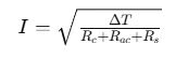
Where:
- I = Ampacity (A)
- ΔT = Maximum permissible temperature rise (K or °C)
- Rc = Thermal resistance of the conductor to the environment (K/W)
- Rac = AC resistance of the conductor (Ohm/m or Ohm/km)
- Rs = Additional losses (shield, dielectric, etc.)
This general formula is more often used in IEC 60287-based systems for buried or bundled conductors.
Simplified Engineering Formula:
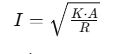
Where:
- I = Current carrying capacity (A)
- K = Proportionality constant based on environment (typically ranges from 0.24 to 0.44 for copper)
- A = Cross-sectional area of conductor (mm²)
- R = Resistance (Ω/km)
NEC Adjustment for Ambient Temperature:
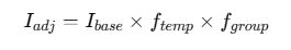
Where:
- Iadj = Adjusted ampacity
- Ibase = Base ampacity from standard tables
- ftemp = Temperature correction factor
- fgroup = Derating factor for more than 3 conductors in a raceway or cable tray
Common Temperature Correction Factors (NEC Table 310.15(B)(2)(a))
| Ambient Temp (°C) | Correction Factor (75°C) |
| 21-25 | 1.05 |
| 26-30 | 1.00 |
| 31-35 | 0.94 |
| 36-40 | 0.88 |
| 41-45 | 0.82 |
| 46-50 | 0.75 |
Real-World Application Examples
Example 1: Residential Feeder Circuit Using Copper Conductor
Scenario: Design a 100A feeder circuit for a residential subpanel using copper THHN conductors in a 40°C ambient environment with 4 conductors in a single conduit.
Step 1: Base Ampacity from Table
- Use 1 AWG copper wire rated for 130A at 75°C insulation.
Step 2: Apply Temperature Correction
- At 40°C: Correction Factor = 0.88
- 130A × 0.88 = 114.4A
Step 3: Apply Grouping Derating (4 Conductors)
- Derating Factor (4 conductors) = 0.80
- 114.4A × 0.80 = 91.52A
Result: 1 AWG copper is insufficient. Upgrade to 1/0 AWG (base ampacity = 150A):
- 150A × 0.88 × 0.80 = 105.6A → Acceptable
Example 2: Industrial Installation Using Aluminum Conductors
Scenario: Supply a 250A three-phase motor panel with aluminum conductors in a cable tray at 30°C, 3 loaded conductors.
Step 1: Choose Base Size
- 350 kcmil aluminum @ 75°C = 250A
Step 2: Ambient Adjustment
- At 30°C: Factor = 1.00 → No change
- 3 conductors → No grouping derating
Result: 350 kcmil aluminum is suitable for 250A load.
Additional Factors Affecting Ampacity
- Conductor Material: Copper has lower resistance than aluminum, resulting in higher ampacity.
- Insulation Type: Higher rated insulation (e.g., 90°C THHN) permits more current.
- Installation Condition: Underground or in air, bundled cables, or ducts impact heat dissipation.
- Voltage Drop: For long runs, ensure voltage drop is <3% for branch circuits (NEC recommendation).